Copper melts near 1985°F while stainless steel requires temperatures closer to 2750°F, and copper’s thermal conductivity pulls heat away so rapidly that the stainless side often overheats or cracks before the copper reaches fusion.
This mismatch is the core problem when learning how to weld copper to stainless steel. Incorrect heat balance produces lack of fusion, copper penetration cracking into the stainless grain boundaries, or brittle intermetallic zones that fail under load or thermal cycling.
The joint appears in heat exchangers, electrical bus bars, chemical process equipment, and cryogenic hardware, where strength, conductivity, and corrosion resistance must coexist.
Success depends on filler selection, controlled heat input, joint geometry that favors heat flow through the stainless, and precise arc placement rather than brute-force amperage.
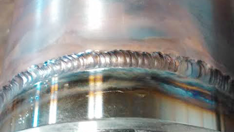
Image by weldingpros
Why Copper and Stainless Steel Resist Conventional Fusion
Copper and stainless steel form an immiscible system in the liquid state. Iron and copper show limited mutual solubility, so uncontrolled mixing creates brittle phases and solidification cracking. Copper’s conductivity is roughly eight times higher than austenitic stainless, turning the copper side into a continuous heat sink.
Differential expansion rates generate residual stress that can open cracks during cooling. Liquid copper can also penetrate stainless grain boundaries, producing liquid-metal embrittlement. These metallurgical realities dictate every subsequent decision: process choice, filler chemistry, preheat, and arc position.
Melting-Point and Conductivity Mismatch
The 700–800°F gap in melting temperature means the stainless must be heated carefully while the copper is still solid or only partially molten. Direct high-current fusion on the copper side usually burns through it before the stainless reaches welding temperature.
Heat must therefore be introduced preferentially from the stainless side so excess energy dissipates into the copper rather than destroying it.
Risk of Intermetallic Formation and Cracking
When iron, chromium, and copper mix freely, hard intermetallic layers form at the fusion line. These layers reduce ductility and create preferential crack paths. Nickel-bearing fillers dilute the iron content and stabilize a more ductile matrix, while silicon-bronze fillers limit dilution by melting at a lower temperature and acting partly as a braze bridge.
Choosing the Right Process for Copper-to-Stainless Joints
TIG (GTAW) remains the most practical process for thicknesses up to roughly ¼ inch in fabrication shops and field work. MIG can increase deposition rate on thicker sections but reduces heat-input control. Stick welding is possible with silicon-bronze electrodes yet produces more slag and less consistent fusion.
Electron-beam welding delivers the highest quality for critical vacuum or high-pressure service but is unavailable to most shops. Brazing with silver or nickel-based alloys is viable when full-strength fusion is unnecessary.
TIG as the Primary Method
TIG allows independent control of heat and filler addition. DCEN polarity concentrates heat in the workpiece. Pulse capability further reduces average heat input on thin gauges. Argon shielding at 15–25 CFH protects both metals from oxidation.
The non-consumable electrode lets the operator bias the arc toward the stainless side and feed filler only when a stable bridge forms.
When MIG or Brazing Becomes Preferable
MIG with ERCuSi-A wire suits production runs on sections thicker than 3/16 inch where travel speed outweighs precision. Brazing is chosen for thin-sheet HVAC transitions or when residual stress must be minimized; the filler melts below the solidus of both base metals and relies on capillary flow rather than fusion.
Filler Metal Selection That Actually Works
Filler chemistry must accommodate 30–50 % dilution from each base metal while remaining ductile and corrosion-resistant. Silicon bronze (ERCuSi-A) and nickel-copper (ERNiCu-7) are the two most reliable commercial options.
Silicon Bronze (ERCuSi-A) Performance
Silicon bronze melts near 1800°F, below both base metals, and flows readily. It produces sound joints for general structural and electrical applications. Tensile strength typically reaches 50–60 ksi.
Corrosion resistance is adequate in most atmospheric and mild chemical environments but inferior to nickel-bearing alloys in marine or chloride service.
Nickel-Copper and Monel-Type Fillers
ERNiCu-7 (approximately 65 % Ni–30 % Cu) forms a ductile solid-solution matrix that tolerates iron dilution without forming continuous brittle phases. Tensile strength approaches 70 ksi with good elongation.
These fillers are preferred for higher-temperature service (up to 1000°F) and corrosive media. Cost is higher, and the arc requires slightly more skill to keep fluid.
Fillers to Avoid
Pure stainless-steel fillers (ER308, ER309) often produce hot cracking because of copper dilution. Pure copper fillers demand excessive preheat and still risk porosity and lack of fusion on the stainless side. Aluminum-bronze fillers can work in specialized cases but introduce additional oxidation challenges under argon.
Joint Design and Surface Preparation Decisions
Joint geometry must compensate for the heat-sink effect of copper. A half-V or single-bevel preparation on the stainless side with a square copper edge concentrates heat where it is needed. Lap joints with copper on top allow gravity-assisted filler flow.
Thorough cleaning is non-negotiable: separate stainless-steel wire brushes for each metal, solvent degreasing, and removal of all oxide immediately before welding.
Bevel and Fit-Up Geometry
For butt joints thicker than 1/8 inch, a 30–45° bevel on the stainless side creates a shelf that holds filler while limiting stainless melting. Root openings of 1/16–3/32 inch help ensure penetration without excessive dilution. Clamping fixtures or chill bars on the stainless side control distortion.
Cleaning Sequence That Prevents Contamination
Copper oxides reform rapidly. Wire-brush copper with a dedicated copper or abrasive pad, then degrease. Stainless receives its own stainless brush. Any cross-contamination of iron particles onto copper or copper particles onto stainless creates inclusions or localized corrosion cells later in service.
Preheat, Amperage, and Arc Placement Parameters
Preheat is applied almost exclusively to the copper side to offset its conductivity. Typical ranges are 200–400°F for thin sheet and up to 500–750°F for heavier sections. Amperage starts lower than pure stainless settings and is adjusted by observation of puddle behavior rather than fixed charts.
Practical Starting Amperage Ranges (TIG, DCEN)
| Thickness (inch) | Amperage Range | Filler Diameter | Approximate Preheat (°F) |
|---|---|---|---|
| 0.062 | 80–110 | 1/16 | 200–250 |
| 0.125 | 110–150 | 1/16–3/32 | 250–350 |
| 0.187–0.250 | 150–200 | 3/32 | 350–450 |
Pulse settings of 1–5 Hz with peak current 150 % of background further reduce heat input on gauges under 1/8 inch.
Arc Initiation and Travel Technique
Strike the arc on the stainless side and hold until a small molten pool forms. Move the arc across the joint line so the stainless pool wets the copper edge. Add filler into the leading edge of the pool rather than directly into the arc.
Maintain a short arc length (less than 1/8 inch) and a travel angle of 10–15° drag. Travel speed is typically 4–7 ipm; slower speeds increase dilution and cracking risk.
Controlling Distortion, Cracking, and Post-Weld Integrity
Rigid fixturing and intermittent tacks every 1–2 inches limit movement. On thicker sections a copper chill bar under the stainless side extracts heat and reduces warpage. After welding, slow cooling under insulation or a controlled post-heat of approximately 400°F for 15–30 minutes relieves residual stress without full annealing.
Visual inspection for undercut, porosity, or uneven toes is followed by dye-penetrant or radiography on critical joints. Mechanical testing of procedure coupons confirms tensile and bend performance before production work proceeds.
Signs of Excessive Heat Input
Stainless discoloration beyond light straw, copper undercut, or a wide flat bead with coarse solidification lines indicate overheating. Reduce amperage or increase travel speed immediately. A properly balanced weld shows a smooth transition, minimal HAZ discoloration on the stainless, and slag-free toes when silicon bronze is used.
Wrapping Up
Selecting silicon bronze or nickel-copper filler, biasing the arc onto the stainless, and preheating only the copper side converts an inherently unstable metallurgical combination into a reliable joint. For critical service the same principles scale to electron-beam or laser processes with beam offset toward the stainless.
The advanced operator further reduces intermetallic thickness by limiting total heat input through pulsed current and multipass sequencing with interpass cleaning, achieving joints that retain both conductivity and structural integrity under cyclic thermal loads.
FAQ
Can you TIG weld copper directly to 304 stainless without filler?
Autogenous welds are possible on thin gauges with careful heat control and beam or arc offset, but strength and ductility are lower and cracking risk rises. Filler is recommended for most structural applications.
What is the best filler rod for copper to stainless steel?
ERCuSi-A (silicon bronze) for general work and ERNiCu-7 for higher corrosion resistance or elevated-temperature service.
Do I need to preheat when welding copper to stainless?
Preheat the copper side only, typically 200–400°F depending on thickness, to compensate for its high thermal conductivity and promote even fusion.
Is MIG welding suitable for copper to stainless steel?
Yes for thicker sections where speed matters; use ERCuSi-A wire, argon or argon-helium shielding, and still control heat input to avoid stainless burn-through.