Welding stainless steel to galvanized steel creates a difficult joint because the two metals respond differently to heat, corrosion, and welding conditions.
The zinc coating on galvanized steel can produce harmful fumes when heated, while direct contact between stainless steel and zinc-coated carbon steel can also create corrosion concerns in the finished joint.
Proper preparation, joint design, filler selection, heat control, and removal of zinc near the weld area are therefore critical.
The challenge is not simply getting the arc to produce a sound bead; the goal is to create a mechanically reliable joint without excessive contamination, porosity, distortion, or premature corrosion.
Understanding welding stainless steel to galvanized steel requires attention to both welding technique and the behavior of the dissimilar metals. The following principles explain how to approach this joint while minimizing common welding and corrosion problems.
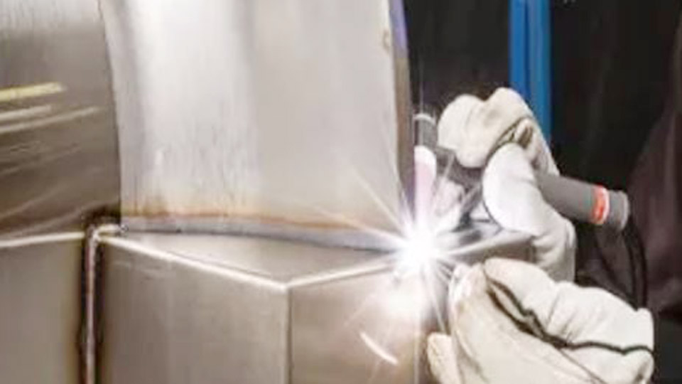
Photo by zhouxianggroup
Why Zinc Removal Determines Weld Integrity on Galvanized-to-Stainless Joints
Zinc melts at approximately 787 °F (420 °C) and boils near 1665 °F (907 °C)—well below steel welding temperatures. When the arc hits intact galvanizing, zinc vaporizes violently inside the weld pool, trapping gas pockets and creating porosity.
The same vapor carries zinc particles onto the stainless surface, where molten zinc can penetrate grain boundaries under residual stress and produce intergranular cracking known as liquid metal embrittlement.
How Far Must the Zinc Coating Be Removed?
AWS guidance and practical experience require clearing the zinc coating 1–4 inches (25–100 mm) on both sides of the intended weld and on both faces of the plate.
Thicker sections or multi-pass welds demand the full 4-inch margin because heat from subsequent passes can still vaporize distant zinc.
Grind until bright, clean carbon steel is exposed. Flap discs (36–60 grit) on an angle grinder remove the coating efficiently without excessive base-metal loss. Wire wheels leave residual zinc particles and are less reliable for critical work.
Consequences of Incomplete Zinc Removal
Any zinc left in the heat-affected zone still vaporizes, producing porosity at the fusion line and undercut. On the stainless side, even microscopic zinc residues can initiate liquid-metal cracks that propagate under service stress.
Visual inspection after grinding is insufficient; wipe the ground area with a clean cloth and inspect under strong light for remaining dull zinc patches.
Selecting Filler Metal That Handles Carbon-Steel Dilution
After zinc removal the joint is stainless to mild or low-alloy steel. Carbon and silicon from the carbon-steel side dilute the weld metal, lowering chromium and nickel content and risking a fully austenitic, crack-sensitive microstructure if the wrong filler is used.
Why 309L Is the Standard Choice
ER309L or E309L contains higher chromium (22–25 %) and nickel (12–14 %) than 308-series fillers. This excess alloy compensates for dilution from the carbon-steel side and maintains a controlled ferrite content (typically FN 5–15) that resists hot cracking.
308L or 308LSi works for stainless-to-stainless but becomes under-alloyed when diluted by carbon steel and is therefore unsuitable for this joint.
For stick welding, E309L-16 or E309L-17 electrodes provide the same chemistry with iron-powder coatings for higher deposition.
Wire and Rod Size Considerations
For TIG, 1/16-inch or 3/32-inch ER309L rods cover most thicknesses up to ¼ inch. MIG uses .030-inch or .035-inch ER309L wire. Larger diameters increase heat input and dilution; keep wire size matched to material thickness so travel speed can stay high enough to limit carbon pickup.
Process Selection for Stainless-to-Galvanized (Post-Removal) Joints
Once the zinc is gone, process choice depends on thickness, position, appearance requirements, and shop versus field conditions.
TIG for Thin Material and Controlled Dilution
TIG delivers the lowest heat input and precise filler addition, ideal for sheet and plate under 3/16 inch. Use pure argon shielding at 15–20 CFH. Keep the arc short and the tungsten angle near 15–20 degrees.
Add 309L filler on the stainless side first when possible so the initial puddle is already high-alloy before contacting the carbon steel. Typical parameters for 1/8-inch material: 80–110 A DCEN, travel 4–6 ipm.
MIG for Speed on Thicker Sections
MIG with ER309L and tri-mix or 98 % argon / 2 % oxygen (or 90/10 Ar/CO₂ for thicker plate) produces acceptable results on 3/16-inch and heavier material. Short-circuit transfer keeps heat low on thinner stock; spray transfer on thicker joints improves wetting.
Voltage and wire-feed speed should be set so the arc stays soft enough to avoid undercutting the stainless side. Typical .035-inch wire settings on ¼-inch plate: 18–22 V, 180–250 ipm wire speed.
Stick Welding for Field and Outdoor Work
E309L stick electrodes tolerate less-than-perfect fit-up and light residual contamination better than gas-shielded processes. Run DCEP, short arc length, and a slight drag angle.
On vertical-up joints reduce amperage 10–15 % from the flat setting to control the fluid slag. Typical range for 1/8-inch electrodes: 90–130 A.
Joint Design and Heat-Input Limits That Protect Both Metals
Stainless expands more than carbon steel and has lower thermal conductivity. Excessive heat widens the HAZ on the stainless side, increases dilution, and raises the risk of carbide precipitation if the stainless is not low-carbon or stabilized.
Bevel and Root-Gap Decisions
For material thicker than 3/16 inch, a single-V or double-V groove with 60–70° included angle and 1/16–3/32-inch root gap allows full penetration without excessive filler volume. On thinner sheet a square butt with tight fit-up and minimal gap reduces heat input.
Fillet welds should be sized only as large as structural requirements demand; oversized fillets add unnecessary heat and dilution.
Controlling Dilution Through Technique
Stringer beads or narrow weaves keep the weld-metal composition closer to the filler chemistry. Wide weaves increase the proportion of melted carbon steel and drop the ferrite number.
When multi-pass welding is required, deposit the first pass with slightly higher travel speed to minimize root dilution, then fill with normal parameters.
Cleaning and Contamination Control on the Stainless Side
Carbon steel particles, grinding dust, or residual zinc on the stainless surface destroy corrosion resistance and can initiate cracking. Dedicate stainless-only wire brushes, grinding discs, and clamps.
After grinding the galvanized side, thoroughly clean both members with acetone or a dedicated stainless cleaner before fit-up. Never use the same flap disc that removed zinc on the stainless surface.
Post-Weld Corrosion Behavior and Surface Restoration
The weld metal and adjacent carbon steel are no longer protected by zinc. The stainless-to-carbon interface creates a galvanic couple in which the carbon steel becomes anodic and corrodes preferentially in the presence of electrolyte.
In outdoor or wet service this area must be protected by coating, paint, or a zinc-rich primer applied after the weld cools and is cleaned.
On the stainless side, remove heat tint by mechanical means or chemical passivation if appearance or full corrosion resistance is required. Avoid chloride-containing cleaners that can initiate pitting.
Inspection Criteria Specific to Dissimilar Stainless-Galvanized Welds
Visual inspection must confirm complete fusion at both toes, absence of porosity, and no undercut deeper than code limits. Dye-penetrant testing reveals surface cracks that may result from residual zinc or excessive restraint.
For critical structural joints, sectioning a test coupon and etching to measure dilution and ferrite content provides quantitative verification that the 309L chemistry performed as intended.
Wrapping Up
Successful welding of stainless steel to galvanized steel rests on three non-negotiable decisions: complete zinc removal from the entire heat-affected zone, use of 309L filler to manage carbon-steel dilution, and heat-input control that limits both dilution and stainless HAZ degradation.
Once those controls are locked in, the joint behaves like any other stainless-to-carbon dissimilar weld and delivers predictable strength and service life.
Advanced fabricators further reduce risk by qualifying a procedure that records actual dilution percentages and ferrite numbers on production-representative coupons rather than relying solely on published filler data sheets.
FAQs
Can you weld stainless steel to galvanized without grinding off the zinc?
No. Residual zinc produces porosity, spatter, toxic fumes, and potential liquid-metal embrittlement cracks in the stainless. Grinding the coating 1–4 inches from the joint on both faces is required for sound welds.
What filler metal is best for stainless to galvanized steel?
ER309L or E309L. The higher chromium and nickel content compensates for dilution from the carbon-steel side after the zinc is removed. 308-series fillers are under-alloyed for this joint.
Is TIG or MIG better for welding stainless to galvanized?
TIG gives tighter dilution control and better appearance on material under 3/16 inch. MIG is faster and practical on thicker sections once zinc is fully removed. Both require 309L filler.
How do you prevent corrosion after welding stainless to galvanized?
Coat or paint the carbon-steel side and the weld zone after cleaning. The stainless-to-carbon interface forms a galvanic couple that accelerates corrosion of the unprotected carbon steel in wet environments.