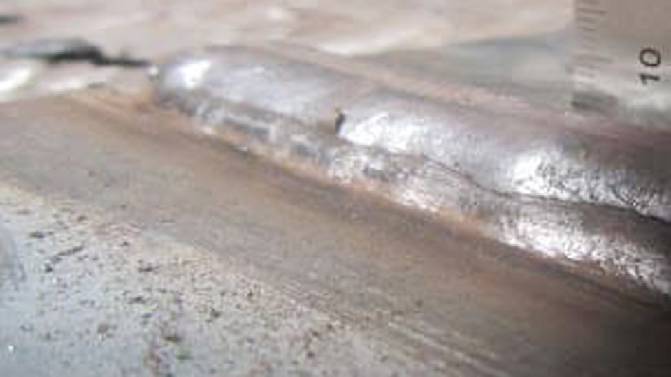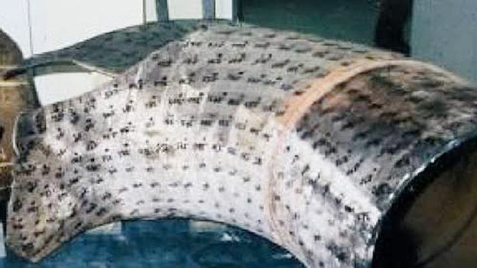
Holes appear in MIG welds as surface pinholes, elongated worm tracks, or complete melt-through voids that ruin joint strength and appearance.
The primary keyword question—what causes holes in MIG welding—points to two distinct mechanisms: trapped gas that forms porosity while the pool solidifies, or excessive heat that melts a path straight through the base metal.
Both defects reject structural and cosmetic work, force costly rework, and signal that shielding, surface condition, heat input, or technique has drifted outside the process window.
Identifying which type of hole is present determines the correct adjustment; treating porosity with lower voltage or burn-through with higher gas flow wastes time and material. Accurate diagnosis starts with the visual pattern and the immediate process variables that produced it.
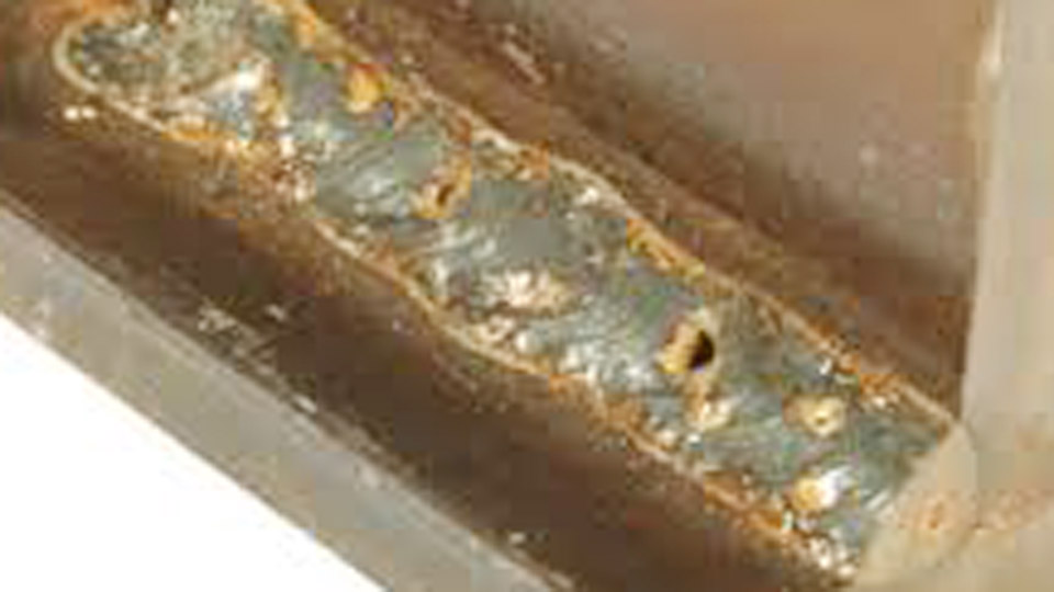
Image by arc-zone
Shielding Gas Failures That Leave Porosity Holes
Inadequate gas coverage allows atmospheric nitrogen and oxygen to dissolve in the molten pool. As the metal freezes, solubility drops and the gas forms spherical or elongated voids.
Flow Rate Outside the Stable Window
Typical solid-wire MIG flow for argon-CO₂ mixes sits between 15–25 CFH (approximately 7–12 L/min) indoors with a standard nozzle. Flow below this range leaves the pool unprotected; flow well above it creates turbulence that aspirates air into the gas column.
The result is scattered surface pinholes or continuous wormhole tracks running along the bead centerline. Measure flow at the nozzle with a flow meter rather than relying solely on the regulator dial, because line restrictions and nozzle condition alter the actual volume delivered.
Leaks, Blocked Nozzles, and Environmental Drafts
A loose fitting, cracked hose, or worn O-ring starves the torch even when the cylinder pressure looks normal. Spatter accumulation inside the nozzle or on the gas diffuser turns laminar flow into jets that leave unprotected zones.
Any draft—shop fan, open door, or outdoor breeze—strips the shield faster than the gas can replenish it. Wormhole porosity that worsens on windy days or appears only on long beads usually traces to one of these coverage interruptions.
Contaminated or Incorrect Gas Supply
Moisture inside the cylinder or downstream of a failed dryer introduces hydrogen that forms fine, evenly distributed pinholes. Using pure CO₂ on thin material or the wrong argon-CO₂ ratio for the alloy can also destabilize the arc and increase gas absorption. Confirm cylinder contents and purge the lines after any cylinder change before resuming production welds.
Surface Contamination That Generates Gas Inside the Pool
Contaminants vaporize under the arc and release gas that becomes trapped if it cannot escape before solidification.
Rust, Oil, Paint, and Mill Scale
Heavy mill scale, rust, residual oil, or paint coatings decompose and liberate gases that produce uniform pinhole porosity or irregular scattered pits. The porosity often concentrates along the centerline or at the toes where the last liquid freezes.
Grinding or wire-brushing to bright metal ½–¾ inch on each side of the joint removes the source. Solvent wiping after mechanical cleaning eliminates residual hydrocarbons that grinding alone can leave behind.
Moisture and Galvanized Coatings
Condensation on cold plate or damp wire introduces hydrogen. Galvanized or zinc-coated steel releases zinc vapor that forms characteristic elongated voids if the pool solidifies too quickly.
Light preheating of cold material drives off surface moisture; zinc coatings require thorough removal or specialized procedures that allow the vapor to escape before the bead freezes.
Technique Variables That Reduce Shield Effectiveness or Overheat the Pool
Gun position and motion control both gas coverage and heat input simultaneously.
Excessive Stickout and Torch Angle
Electrode extension beyond ½ inch reduces current and weakens the gas envelope around the arc. A steep push angle or extreme drag angle can divert the gas stream away from the trailing edge of the pool, leaving a sooty, pitted surface. Maintain stickout in the ⅜–½ inch range and a travel angle of 5–15 degrees so the nozzle remains centered over the active pool.
Travel Speed and Arc Length Inconsistencies
Travel that is too fast leaves insufficient time for dissolved gas to rise and escape, freezing porosity in place. An excessively long arc length increases the volume of unprotected metal and raises the chance of atmospheric contamination. Consistent moderate travel that keeps the arc at the leading edge of the pool allows gas to escape while the metal is still fluid.
Distinguishing Burn-Through Holes from Porosity
Burn-through is not gas-related; it is the complete melting of a hole through the base metal caused by heat input exceeding the material’s ability to conduct heat away.
Heat Input on Thin Gauge Material
On sheet under ⅛ inch (3 mm), voltage and wire-feed speed that would be appropriate for thicker plate create a fluid pool that drops through under gravity. Short-circuit transfer with lower voltage (typically 16–19 V) and reduced wire speed keeps the heat manageable.
Increasing travel speed further limits dwell time in any one spot. Using a smaller-diameter wire (0.023–0.030 inch) also reduces heat for a given voltage setting.
Fit-Up Gaps and Localized Dwell
A root gap wider than the process can bridge leaves the pool unsupported. Stopping or slowing at the same location repeatedly concentrates heat until the metal melts through. Tight fit-up, copper or steel backing bars, and stitch or skip welding sequences prevent the pool from collapsing through thin or poorly supported joints.
Equipment and Consumable Conditions That Contribute to Holes
Mechanical and consumable issues often masquerade as parameter problems.
Nozzle, Contact Tip, and Liner Condition
Spatter-blocked nozzles and worn contact tips disrupt both gas flow and wire presentation. A dirty or kinked liner introduces intermittent feed that produces arc instability and localized overheating or gas loss. Regular nozzle cleaning and tip replacement restore laminar shielding and stable current transfer.
Wire Surface and Storage
Rusted, oily, or moisture-laden wire feeds contaminants directly into the arc. Store solid wire in a dry environment and discard any spool that shows surface oxidation or residue.
Self-shielded flux-cored wire has its own polarity and technique requirements; running it on the wrong polarity or with a push technique frequently produces porosity that looks identical to gas-shielded defects.
Decision Sequence for Identifying and Correcting the Cause
Begin with the visual signature. Scattered fine pinholes or worm tracks point first to shielding gas or surface contamination. A clean, round hole with melted edges and no surrounding porosity indicates burn-through from heat or fit-up. Check gas flow and nozzle condition, then inspect and clean the joint, then verify stickout and travel consistency.
Only after those variables are controlled should voltage or wire speed be adjusted. Record the corrected settings against material thickness and joint type so the same combination can be recalled without repeating the diagnostic cycle.
Holes in MIG welds are rarely random; they map directly to measurable process departures. Matching the defect appearance to the responsible variable—gas coverage, surface condition, heat input, or technique—allows the operator to restore sound metal without trial-and-error parameter changes.
Advanced practice further reduces risk by combining short stickout, consistent travel, and pre-weld verification of gas delivery on every shift, ensuring the pool remains both protected and properly supported until solidification is complete.
FAQs
Why does my MIG weld have tiny holes on the surface?
Surface pinholes almost always indicate porosity from inadequate shielding gas coverage or surface contamination. Verify flow rate, nozzle cleanliness, and absence of drafts first, then clean the joint to bright metal.
What causes wormhole porosity in MIG welding?
Wormhole tracks form when gas is trapped and forced to escape along the solidifying centerline, usually from disrupted gas flow, long stickout, or heavy surface contamination that releases gas late in the freeze cycle.
How do I stop burning holes through thin metal with MIG?
Reduce voltage and wire-feed speed into the short-circuit range, increase travel speed, use smaller-diameter wire, and maintain tight fit-up or backing. Avoid dwelling in one location on material under ⅛ inch.
Can dirty welding wire cause holes in the bead?
Yes. Rust, oil, or moisture on the wire surface introduces gas or hydrogen that appears as porosity. Replace contaminated spools and store wire in a dry environment.