The wire feed motor sits silent while the fan runs and the relay clicks. No wire advances, the arc never starts, and the job stops. A Lincoln welder wire feed motor not working is one of the most frequent service calls on MIG machines from the Weld-Pak and Pro-MIG series through Power MIG units.
When the motor fails to turn, every downstream process fails with it—drive rolls stay locked, the liner stays empty, and voltage alone cannot produce a weld.
Correct diagnosis separates a $15 trigger switch or dried gearbox grease from a control board replacement, preventing unnecessary parts swaps and restoring feed speed control within the machine’s designed voltage and current limits.
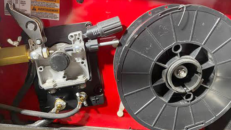
Image by r/Welding
Isolating the Failure Before Opening the Case
Start by confirming the exact symptom set. Power the machine and pull the gun trigger while watching and listening.
Fan Runs but Drive Rolls Stay Still
This pattern points away from main power input and toward the control or motor circuit. Note whether a relay or contactor clicks. A click confirms the trigger signal reached at least part of the control board; absence of a click moves attention upstream to the gun switch or its wiring.
Motor Hums Without Rotation
Voltage is reaching the armature but torque is insufficient to overcome mechanical resistance. This classic signature almost always traces to a seized plastic gearbox filled with hardened factory grease, especially on machines stored unused for years or run in hot shops.
Intermittent or Speed-Dependent Failure
The motor starts only at higher wire-speed settings or after the voltage selector is rotated through its positions. Dirty contacts in the rotary voltage switch or a failing speed potentiometer produce this behavior on older SP and Weld-Pak models.
Trigger Circuit Tests That Eliminate the Gun First
The gun trigger is the most abused component and the fastest to verify.
Continuity Check Across Trigger Pins
Unplug the welder. Locate the trigger leads at the gun receptacle or internal connector (often the two smaller pins on a four-pin Euro-style plug). Set a multimeter to continuity or low ohms. Squeeze the trigger; the reading should drop near zero.
An open circuit means the switch contacts or internal cable conductors have failed. Replacement trigger assemblies for Magnum-style guns cost little and install in minutes.
Jumper Test at the Machine Connector
Bridge the two trigger pins with a short length of wire while the machine is powered. If the motor now runs, the fault is confined to the gun or its cable. If the motor remains dead, the problem lies inside the welder—fuse, board, wiring, or motor itself.
Measuring Voltage at the Motor Terminals
Once the trigger path is proven good, quantify the signal the control board actually delivers.
Expected DC Voltage Ranges
With the machine powered, wire-speed control at maximum, and trigger closed, probe the two motor leads (commonly labeled 539 and 541 on Lincoln schematics). Compact 120 V units typically show 8–24 V DC; larger feeders can reach higher values proportional to the speed setting.
Zero or near-zero voltage with a known-good trigger indicates a failed board output stage, open fuse on the control secondary, or oxidized voltage-selector contacts.
Interpreting Low or Unstable Readings
Voltage present but well below the normal band, or fluctuating with trigger pressure, points to high-resistance connections, a failing potentiometer, or corroded diode bridges that supply the motor drive circuit.
Cycling the voltage selector switch through every position several times often restores contact on older machines and restores full voltage.
Direct Bench Test of the Motor Itself
Remove electrical variables by powering the motor independently.
12 V Battery Application
Disconnect the motor leads, noting polarity. Apply a 12 V battery or DC supply directly to the terminals. A healthy permanent-magnet DC motor spins freely at high RPM with a clean whine. Failure to spin, excessive current draw, or rapid heating confirms internal problems—worn brushes, shorted armature, or seized bearings.
Brush Length Inspection
Many Lincoln motors allow brush access after the end cap is removed. Brushes shorter than ¼ inch (6 mm) lose spring pressure and contact area; replacement restores torque without replacing the entire motor assembly. Measure armature resistance across the terminals; typical values fall between 5–20 ohms on good motors.
Gearbox Seizure—The Most Common Mechanical Cause
On Weld-Pak, Pro-MIG 140/175, and similar compact models, the motor drives a multi-stage nylon gear train packed with grease at the factory.
Symptoms of Hardened Grease
The motor receives correct voltage and may even hum, yet the output shaft and drive rolls remain locked. Attempting to turn the rolls by hand with tension released meets firm resistance.
Cleaning and Relubrication Procedure
Remove the motor/gearbox assembly (usually held by a few screws). Extract the four Torx (commonly T20) screws on the gearbox cover. Clean every gear and the housing of the dried, chunky grease.
Apply a light film of molydisulfide grease (Lincoln specification E2322 or equivalent high-temperature synthetic). Avoid graphite greases that can become conductive.
Reassemble carefully, verifying correct motor rotation direction—reversed leads reverse feed direction and push wire backward.
This single repair restores many machines that appear to have “dead” motors.
Control Board, Fuse, and Power-Supply Failures
When voltage never appears at the motor leads, attention shifts to the printed circuit board and its supplies.
Fuse and Secondary Power Checks
Locate any glass or ceramic fuses on the control transformer secondary or board itself (often 3–5 A). Continuity must be present. Some units also protect the motor circuit with a thermal or solid-state overload that resets after cooling; confirm the machine has not been run into a bird-nest overload immediately before failure.
Visual and Thermal Inspection of the Board
Look for discolored resistors near the motor-drive transistors, swollen electrolytic capacitors, cracked solder joints, and burned traces. Heat damage concentrates around the wire-speed control section on many 140- and 180-class boards after years of shop use.
On machines with rotary voltage taps, oxidized switch contacts interrupt power to the entire control circuit even while the fan continues to run; rotating the switch repeatedly or cleaning the contacts frequently restores function.
Relay Confirmation
A distinct click without subsequent motor voltage often means the control relay has closed but its contacts or downstream wiring have failed. Measuring voltage on both sides of the relay isolates the open path.
Model-Specific Patterns on Popular Lincoln Units
Compact 120 V machines (Weld-Pak 100/140, SP-125/135/140, Pro-MIG series) share the same plastic gearbox vulnerability and low-voltage motor circuits.
Power MIG 210/255-class units add tachometer feedback and more sophisticated overload protection; a failed tach or hall-effect sensor can produce speed instability even when the motor itself is healthy.
Larger LN-series feeders use higher armature voltages and more robust brush systems, so brush wear and control-cable faults appear more often than total gearbox lock-up.
Always match replacement motors or boards to the exact model and serial number; wire-speed calibration and mounting dimensions differ across generations.
Decision Path for Permanent Resolution
Measure voltage at the motor first. Zero voltage with a good trigger points to fuse, switch, or board. Correct voltage with no rotation points to gearbox or motor. Direct 12 V testing separates a dead motor from an upstream electrical fault.
Cleaning the gearbox recovers the majority of “hum but no turn” cases without parts cost. Only after these checks does board or motor replacement become the logical next step.
Keeping the spool brake light, drive-roll pressure correct, and liner clean prevents the overloads that accelerate both electrical and mechanical failure.
Wrapping Up
When the motor finally turns under proper voltage and the drive rolls advance wire at the selected speed without surge or hesitation, feed consistency returns and arc starts become predictable again.
Advanced operators monitor armature current under load (typically under 2–3 A on compact units); rising current with no mechanical restriction signals impending motor or gearbox wear long before total stoppage occurs.
FAQs
Why does my Lincoln welder motor hum but the rolls do not turn?
Hardened grease has locked the plastic gearbox. Voltage reaches the motor, but torque cannot overcome the bind. Clean and relubricate the gears.
How do I test if the wire feed motor itself is bad?
Disconnect the motor leads and apply 12 V DC directly. Smooth high-speed rotation means the motor is good; no rotation or rapid heating means replace brushes or the motor.
What voltage should appear at the motor terminals on a Lincoln MIG?
With trigger closed and speed at maximum, expect roughly 8–24 V DC on most compact models. Zero voltage indicates a board, fuse, or switch problem upstream.
Can a bad gun trigger stop the wire feed motor completely?
Yes. An open trigger circuit prevents the control board from energizing the motor. Jumper the trigger pins at the machine; if the motor runs, replace the gun switch or cable.