A Miller Suitcase feeder that fails to feed wire smoothly, produces birdnesting at the drive rolls, or delivers an unstable arc usually traces back to one of three setup errors: incorrect polarity relative to the wire, a poorly seated voltage-sensing clamp, or mismatched drive-roll pressure.
Learning how to set up a Miller Suitcase welder correctly eliminates those failures before the first arc is struck. These voltage-sensing feeders (SuitCase X-TREME 12VS, ArcReach SuitCase 12, and related models) draw operating power from the welding circuit itself and therefore depend on precise cable routing, polarity matching, and mechanical alignment.
Proper setup determines whether the feeder delivers consistent wire speed across 50–780 ipm, maintains stable arc voltage feedback, and supports both solid-wire MIG and flux-cored processes on the same power source.
The decisions made during connection and loading directly control deposition rate, bead profile, and the ability to run remote voltage adjustment on ArcReach-equipped machines.
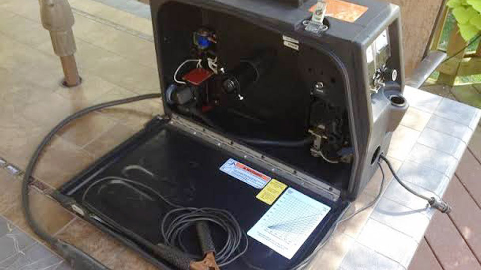
Image by weldingweb
Matching Power Source Type and Process Mode to the Suitcase Feeder
Miller SuitCase feeders operate exclusively on DC power sources that can deliver either constant-voltage (CV) or constant-current (CC) output. AC sources are not recommended because the voltage-sensing circuit and contactor expect unidirectional current.
CV Versus CC Power Source Selection
CV mode is preferred for most solid-wire MIG and gas-shielded flux-cored work because arc length remains relatively constant as stick-out varies. CC mode can be used, especially with self-shielded flux-cored wires, but wire-feed speed then becomes more sensitive to arc voltage changes.
Many engine-driven machines (Big Blue, Trailblazer) automatically switch process modes when a SuitCase is detected on the electrode terminal; others require manual selection of the GMAW/FCAW position.
Confirm the power source is set to DC and that open-circuit voltage falls within the feeder’s 14–110 V operating window before connecting cables.
Polarity Decisions Driven by Wire Type
Polarity is determined by the electrode manufacturer, not by the feeder. Solid ER70S-6 and most gas-shielded flux-cored wires run electrode positive (DCEP). Many self-shielded flux-cored wires require electrode negative (DCEN).
Connect the weld cable from the power-source electrode stud to the feeder input terminal according to the wire data sheet. Reverse polarity produces excessive spatter, poor penetration, or an unstable arc that no amount of voltage or speed adjustment will correct.
On ArcReach-equipped systems the power source senses the feeder connection and may auto-select the process; still verify polarity matches the wire before welding.
Cable Routing, Voltage-Sensing Clamp, and Work-Lead Placement
The SuitCase receives both welding current and control power through the weld cables. Incorrect routing or a dirty sensing clamp is the most common cause of “feeder will not power up” complaints.
Connecting the Weld Cable and Work Lead
Shut down the power source and stop any engine-driven unit. Route a properly sized weld cable from the power-source electrode terminal to the feeder’s power-input connector (Tweco-style or equivalent).
Size the cable for the expected current and total length; undersized cable produces voltage drop that starves the feeder motor and collapses arc voltage.
Connect the work lead from the power-source work terminal directly to the workpiece. Keep both cables as short and straight as practical to minimize inductive reactance and voltage drop.
Voltage-Sensing Clamp Placement and Contact Quality
The voltage-sensing lead leaving the feeder must clamp to clean, bare metal on the workpiece. This lead is not a ground; it supplies arc-voltage feedback that powers the motor-control board and enables accurate wire-speed regulation.
Attach it close to the weld zone but outside the immediate heat-affected area. Paint, rust, or mill scale under the clamp causes intermittent sensing, erratic feed, or complete loss of power to the feeder. On long runs, secure the sensing lead so it cannot be damaged by traffic or hot slag.
Drive-Roll Selection, Wire Loading, and Pressure Adjustment
Mechanical feed problems dominate field failures once electrical connections are correct. Drive-roll geometry and pressure must match the wire diameter and type exactly.
Matching Drive Rolls to Wire Diameter and Construction
V-groove rolls are used for solid hard wire (.023–.052 in). Knurled or V-knurled rolls grip flux-cored wire (.030–5/64 in) without crushing the sheath. Install the correct size with the marked diameter facing the operator; the size stamped on the upward face is the active groove.
Align inlet and outlet guides so the wire travels in a straight path through the rolls. Misaligned guides create friction that the motor must overcome, reducing available feed speed and accelerating liner wear.
Setting Drive-Roll Pressure Without Deforming Wire
Begin with zero pressure. Hold the gun at approximately 45° and two inches above a wood block. Depress the trigger and gradually increase pressure until the wire stops slipping on the roll surface, then add one-half additional turn.
Excessive pressure flattens solid wire or collapses flux-cored sheaths, producing birdnesting at the rolls or erratic arc behavior.
Insufficient pressure allows slip under load, especially on long gun cables or when feeding large-diameter cored wire. Re-check pressure after the first few pounds of wire because new rolls seat slightly.
Threading Wire and Installing the Gun
Load the spool so wire pays off from the bottom. Thread through the inlet guide, drive rolls, and outlet guide, then into the gun power pin.
Remove the contact tip, feed wire through the liner until it exits the gun neck, reinstall the tip, and trim stick-out to ⅜–½ in.
Confirm the gun’s O-rings are intact if gas-shielded welding will be used; damaged seals allow air aspiration that produces porosity even with correct gas flow.
Gas System Configuration for Shielded Processes
Self-shielded flux-cored wire requires no gas. Gas-shielded MIG and flux-cored processes demand a clean, regulated supply limited to 100 psi maximum at the feeder inlet.
Connect a regulator appropriate for the cylinder (CGA-580 for most Ar/CO₂ mixes) and route a welding-grade gas hose to the feeder’s gas inlet fitting. Set flow at the regulator for 20–30 CFH under typical shop conditions; higher flows waste gas and can aspirate air at the nozzle.
Use the feeder’s purge function (if equipped) to clear air from the line before the first weld. Verify flow at the gun nozzle with the trigger depressed and wire feed disabled. Restrictors or dirty solenoid valves inside the feeder reduce actual flow even when the regulator reads correctly.
Establishing Starting Parameters and Verifying Arc Performance
Wire-feed speed is set at the SuitCase; voltage is set at the power source unless ArcReach remote control is active. Typical starting points for mild steel with .035 in ER70S-6 solid wire and C25 gas on ¼ in plate are 24–28 V and 250–350 ipm.
Self-shielded .045 in flux-cored wire often runs 22–26 V at 300–400 ipm on DCEN. These values are starting references only; final settings depend on joint fit-up, position, and desired penetration.
Strike a test bead on scrap of identical thickness and joint geometry. Listen for a steady sizzle rather than a sharp crackle or pop.
Inspect the bead for consistent width, proper toe fusion, and clean slag release (flux-cored). Adjust voltage first for arc length and wetting, then wire speed for deposition rate.
On ArcReach systems the voltage control at the feeder communicates through the weld cables, eliminating trips back to the power source.
Confirm that the power source remains in the correct process mode after the first arc is established; some machines default to stick if sensing is lost.
Diagnosing Setup-Related Arc and Feed Failures
When wire burns back into the tip, check drive-roll pressure, liner condition, and contact-tip bore diameter. When the feeder runs but the arc extinguishes immediately, verify polarity and sensing-clamp contact.
Intermittent feed at higher speeds usually indicates a worn liner or insufficient motor torque caused by voltage drop in undersized weld cables. Contactor chatter on older non-ArcReach feeders can result from open-circuit voltage outside the 14–48 V preferred operating band.
Measure voltage at the feeder input under load; more than a 2–3 V drop from the power-source terminal points to cable or connection resistance.
Correct cable sizing, clean sensing contact, matched drive rolls, and polarity that follows the wire data sheet resolve the majority of field problems. Once those four elements are verified, parameter adjustment becomes straightforward and repeatable across shifts and operators.
Wrapping Up
Selecting the correct polarity for the wire, seating the voltage-sensing clamp on clean metal, and setting drive-roll pressure just above the slip point produce stable feed and consistent arc characteristics from the first weld.
Advanced operators further refine performance by matching cable cross-section to total circuit length and by using ArcReach remote voltage control to keep heat input constant as stick-out changes during positional work, eliminating the need to return to the power source mid-joint.
FAQs
What polarity do I use for a Miller Suitcase with solid MIG wire?
Use electrode positive (DCEP) for ER70S-6 and most solid steel wires. Connect the weld cable from the power-source positive terminal to the feeder.
Why does my Miller SuitCase feeder have no power?
Confirm the voltage-sensing clamp is attached to clean workpiece metal and that the power source is producing open-circuit voltage in the 14–110 V range. A dirty clamp or reverse polarity is the most frequent cause.
Can I run flux-cored wire on a Miller SuitCase X-TREME 12VS?
Yes. Install knurled drive rolls matched to the wire diameter, set polarity per the wire manufacturer (often DCEN for self-shielded), and select the appropriate process mode on the power source.
How do I set drive-roll pressure on a SuitCase feeder?
Start at zero pressure, feed wire onto a wood block at 45°, increase until slip stops, then add one-half turn. Excess pressure deforms the wire and causes birdnesting.