Choosing the correct Lincoln Welder Settings Chart is one of the most important steps in producing strong, consistent welds. Voltage, amperage, wire feed speed, and material thickness all work together, and even small setting errors can lead to poor penetration, excessive spatter, lack of fusion, burn-through, or unnecessary rework.
While Lincoln Electric provides recommended parameters for different welding processes and materials, knowing how to interpret those settings is just as important as following them.
A properly matched setup improves arc stability, bead appearance, and overall weld quality while reducing the chance of defects that may fail inspection or compromise structural integrity.
I’ll explain how to use a Lincoln welder settings chart effectively, understand the factors that influence machine settings, and make practical adjustments for different metals, thicknesses, and welding applications with greater confidence.
Understanding Lincoln Welder Controls and Why Settings Matter
Lincoln welders feature intuitive controls: voltage primarily sets arc length and heat, while wire speed (or amperage on CC machines) controls deposition rate. On synergic models, selecting material, wire diameter, and thickness auto-populates base parameters that you fine-tune.
Incorrect settings lead to cold laps on thick material or burn-through on thin stock. Real-world adjustments account for joint type, position, fit-up, and environmental factors like wind or temperature.
Key Factors Influencing Settings
Material thickness dictates baseline heat input. Wire or electrode diameter scales current capacity. Shielding gas composition affects arc characteristics— C25 (75% Ar/25% CO2) offers good penetration and low spatter on mild steel, while 100% argon suits aluminum TIG.
Polarity (DCEP for most MIG/stick, DCEN for TIG steel) impacts penetration and electrode consumption. Contact tip to work distance (CTWD) typically runs 3/8–3/4 inch for MIG; deviations require voltage or WFS compensation.
Machine-Specific Considerations
Power MIG 210 MP or similar multi-process units use synergic modes for quick setup but allow manual override. Older transformer machines rely on coarse/fine voltage taps and amperage dials.
Always reference the machine’s door chart or manual for model-specific ranges, then verify with a test weld on scrap matching your project.
MIG Welding Settings for Mild Steel
MIG (GMAW) with solid wire and shielding gas delivers high productivity on mild steel. Use ER70S-6 wire for its deoxidizers that handle light rust or mill scale.
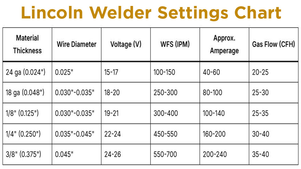
Thickness-Based MIG Chart (ER70S-6, C25 Gas, DCEP)
| Material Thickness | Wire Diameter | Voltage (V) | WFS (IPM) | Approx. Amperage | Gas Flow (CFH) |
|---|---|---|---|---|---|
| 24 ga (0.024″) | 0.025″ | 15-17 | 100-150 | 40-60 | 20-25 |
| 18 ga (0.048″) | 0.030″-0.035″ | 18-20 | 250-300 | 80-100 | 25-30 |
| 1/8″ (0.125″) | 0.030″-0.035″ | 19-21 | 300-400 | 100-140 | 25-35 |
| 1/4″ (0.250″) | 0.035″-0.045″ | 22-24 | 450-550 | 160-200 | 30-40 |
| 3/8″ (0.375″) | 0.045″ | 24-26 | 550-700 | 200-240 | 35-40 |
Start in short-circuit transfer for thin material (lower voltage) and transition toward spray transfer above ~180-200A for thicker plates. Increase voltage 1-2V for out-of-position work to maintain puddle control.
Flux-Cored (FCAW) Settings Without Gas
Self-shielded flux-cored wire (e.g., NR-211-MP or E71T-GS) excels outdoors. Settings run slightly higher voltage than solid wire due to different transfer characteristics.
| Thickness | Wire Diameter | Voltage (V) | WFS (IPM) | Amperage |
|---|---|---|---|---|
| 18 ga | 0.030″ | 16-18 | 60-80 | 50-90 |
| 1/8″ | 0.035″ | 18-20 | 90-130 | 90-140 |
| 1/4″ | 0.045″ | 20-22 | 140-190 | 140-190 |
Use DCEN polarity on many flux-cored wires for better penetration and less spatter. Increase CTWD to 3/4–1 inch.
Stick Welding (SMAW) Parameters
Stick remains versatile for field repairs and thick material. Electrode selection drives settings.
Common Electrode Amperage Chart (Mild Steel, Flat Position)
| Electrode (AWS) | Diameter | Amperage Range | Polarity | Typical Use |
|---|---|---|---|---|
| E6010 | 3/32″ | 40-70 | DCEP | Root passes, pipe |
| E6010 | 1/8″ | 75-130 | DCEP | All positions |
| E6011 | 1/8″ | 75-120 | AC/DC | General fabrication |
| E7018 | 1/8″ | 110-160 | DCEP | Structural, low-hydrogen |
| E7018 | 5/32″ | 130-210 | DCEP | Heavy plate |
Maintain a 1/8–3/16″ arc length. Whip or drag technique varies by rod—E6010 requires whipping for keyhole control. Preheat heavy sections (>1/2″) to 200-300°F to reduce cracking risk with low-hydrogen rods.
Vertical and Overhead Adjustments
Reduce amperage 10-20% from flat settings. Use stringer beads or slight weave; faster travel speed prevents undercut. For E7018 vertical-up, employ a slight “U” or “J” weave with pause at toes.
TIG Welding Settings (GTAW)
TIG produces the highest quality welds on thin or critical applications.
TIG Parameter Chart
| Material / Thickness | Tungsten Dia. | Polarity | Amps | Gas Flow (CFH) | Filler Dia. | Travel (IPM) |
|---|---|---|---|---|---|---|
| Mild Steel 1/16″ | 1/16″ | DCEN | 80-130 | 5-10 | 1/16″ | 8-12 |
| Mild Steel 1/8″ | 3/32″ | DCEN | 130-180 | 9-13 | 3/32″ | 6-10 |
| Aluminum 1/8″ | 3/32″ | AC | 100-150 | 13-17 | 3/32″ | 8-12 |
| Stainless 1/8″ | 3/32″ | DCEN | 100-150 | 9-13 | 3/32″ | 6-10 |
Use 2% thoriated or lanthanated tungsten. For aluminum, balance control favors more EN (electrode negative) for cleaning. Pulse settings (e.g., 1-2 Hz) improve control on thin material.
Advanced Techniques and Process-Specific Decisions
Pulse MIG on Lincoln Machines
Pulse MIG reduces heat input while maintaining deposition—ideal for thin stainless or out-of-position work. Typical parameters: peak current 1.5-2x background, 50-150 Hz frequency. On Power Wave models, select Precision Pulse or RapidArc modes and adjust trim for arc length.
Stainless and Aluminum Considerations
For stainless (ER308L), drop voltage 1-2V vs. mild steel to control heat and avoid sensitization. Tri-mix gas (90% He/7.5% Ar/2.5% CO2) enhances wetting. Aluminum demands push technique, higher WFS, and pure argon. Clean oxide thoroughly; use spool gun for MIG to prevent feeding issues.
Multi-Pass and Joint Design Impacts
Groove joints on thick plate require root pass at lower settings for penetration without burn-through, followed by fill/cap passes at higher deposition. Fillet welds on 1/4″ plate often use 0.045″ wire at 22-24V / 400-500 IPM. Account for joint gap—wider gaps need more filler and adjusted travel speed.
Troubleshooting Common Setting-Related Issues
Porosity often traces to insufficient gas flow, dirty material, or incorrect voltage causing unstable arc. Undercut signals excessive voltage or travel speed.
Convex beads indicate low voltage/high WFS; concave suggests the opposite. Monitor duty cycle on inverter machines during long runs—high-output settings reduce available time.
Adjust for position: overhead MIG may need 1-2V lower and faster travel. Windy conditions demand higher gas flow or flux-cored switch.
Real-World Application Insights
On a typical trailer repair involving 1/8″ to 1/4″ mild steel, start with the MIG chart for 0.035″ wire, test on scrap, then fine-tune WFS for consistent bead height.
For structural stick work, E7018 at recommended amps ensures X-ray quality with proper preheat and interpass temperature control. Pro welders log successful settings per machine and material for repeatability across jobs.
Mastering the Lincoln Welder Settings Chart boils down to matching parameters to thickness, process, and conditions, then verifying through test welds. This approach minimizes defects, optimizes productivity, and delivers professional results consistently.
The advanced insight: true expertise lies in understanding how small trim adjustments interact with waveform controls on modern inverters to manipulate puddle fluidity and travel speed far beyond basic charts—experiment deliberately on production scrap to push weld quality boundaries.
FAQ
What is the best starting voltage for 1/4″ mild steel MIG on a Lincoln welder?
22-24V with 0.035-0.045″ wire at 450-550 IPM WFS using C25 gas. Fine-tune based on puddle behavior and penetration.
How do Lincoln flux core settings differ from solid wire MIG?
Flux core typically uses higher voltage and DCEN polarity with no external gas. Expect slightly faster travel speeds due to built-in shielding.
What amperage for 1/8″ E7018 stick electrode?
110-160A DCEP in flat position. Reduce 10-15% for vertical or overhead.
Do I need different settings for aluminum on Lincoln TIG vs MIG?
Yes—aluminum TIG uses AC polarity and higher gas flow; MIG requires spool gun, push angle, and pure argon with elevated WFS. Always clean material aggressively.