Many welders struggle with inconsistent arc control, unpredictable heat, and failed welds—often because their TIG welder’s foot pedal is wired incorrectly. The Tig welder foot pedal wiring diagram is not just a technical drawing; it’s the foundation for smooth, responsive control.
Whether you’re setting up a custom pedal, repairing a broken one, or troubleshooting erratic amperage, understanding this diagram is vital. A well-wired pedal can transform your welding, giving you precise heat adjustment and cleaner results.
Let’s dive deep into how these pedals connect, what wiring matters, and how to choose or fix the right configuration for your setup.
Image by manuals
What Is A Tig Welder Foot Pedal And Why Wiring Matters
How The Foot Pedal Controls Amperage
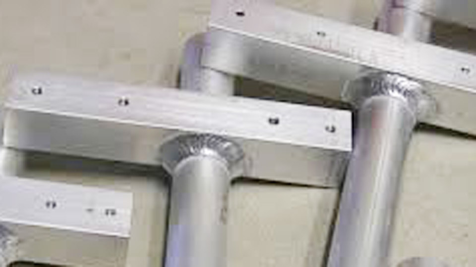
A TIG welder foot pedal acts as a remote control for amperage adjustment. When you press the pedal, it increases current to the torch; releasing it lowers the current. This lets you control heat in real time, making it possible to weld thin metals without burning through or to taper off at the end of a weld.
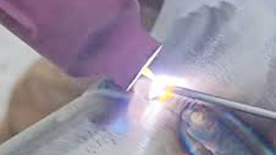
Imagine welding a thin aluminum sheet: too much current will melt a hole, but with a pedal, you can back off instantly as you see the puddle forming. This is why many professional welders refuse to work without a properly functioning foot pedal.
Wiring’s Role In Pedal Function
Wiring is crucial because the pedal uses a variable resistor (often a potentiometer or rheostat) to send signals to the welder. If wired wrong, the pedal might:
- Fail to control current smoothly
- Cause erratic arc behavior
- Make the welder unsafe to operate
Many beginners overlook that even a single wire in the wrong spot can cause unpredictable results. For example, the torch could start unexpectedly, or the pedal may “jump” between amperages instead of moving smoothly. Good wiring is not just a technicality—it’s the difference between professional results and frustration.
Common Pedal Types And Wiring Differences
Most pedals fit into two categories:
- Potentiometer-based: Standard for modern digital TIG welders.
- Rheostat-based: Used in older or industrial machines.
Each type uses different wiring, connectors, and resistance values. For instance, a modern Miller pedal uses a 10kΩ potentiometer, while some older machines use a 25kΩ rheostat. Plugging in the wrong type can either limit pedal range or, worse, damage the control board.
Always check the welder’s specifications before modifying or replacing a pedal.
Anatomy Of A Tig Welder Foot Pedal
Main Components
A typical TIG foot pedal includes:
- Potentiometer or rheostat
- Gear mechanism (to translate pedal movement)
- Cable and connector (often 3- or 5-pin)
- Return spring
- Housing and pedal
The potentiometer or rheostat is the heart of the pedal. It acts like a dimmer switch, adjusting resistance as you press down. The gear mechanism ensures smooth, gradual movement, converting the pedal’s rotation into precise electrical changes. The cable and connector bring signals from the pedal to the welder.
Inside the housing, the return spring ensures the pedal comes back to the “off” position when you lift your foot, an often-overlooked detail that keeps you safe and improves weld consistency.
Internal Wiring Paths
Inside the pedal, wires connect the potentiometer or rheostat to the cable, which goes to the welder. The wiring diagram shows:
- Which pins control amperage
- Which pins activate the torch (on/off)
- Ground or reference pins
A well-laid-out pedal keeps these wires tidy and away from moving parts. Poorly routed wires can wear out quickly from repeated pedal movement, leading to intermittent faults that are difficult to diagnose. Some advanced pedals even use shielded wiring to prevent electrical noise from affecting the signal.
Typical Connector Types
Pedal connectors vary by brand and model. Common types:
- 3-pin: Amperage control only
- 5-pin: Amperage plus torch on/off
- Circular metal connectors or plastic plugs
Here’s a quick comparison:
| Connector Type | Functions | Common Brands |
|---|---|---|
| 3-pin | Amperage control | Lincoln, ESAB |
| 5-pin | Amperage + torch on/off | Miller, Everlast |
| Circular metal | Amperage + on/off | Older machines |
Some welders may use even more complex connectors with up to 8 pins, especially if they support extra features like pulse modulation or remote start. Always count the pins and inspect for bent or damaged contacts before connecting a new pedal.

Credit: www.mig-welding.co.uk
Understanding The Tig Welder Foot Pedal Wiring Diagram
Key Elements Of The Diagram
A wiring diagram shows:
- The potentiometer (marked with resistance rating, e.g., 10kΩ)
- Cable wires (color-coded)
- Connector pins (numbered and labeled)
- Switch (for torch on/off)
You’ll often see lines representing wires, with labels for each connection point. A clear diagram removes guesswork, especially when repairing or building your own pedal. If you don’t have a diagram, take detailed photos before disassembly—many pedals look simple but have surprising wire routing inside.
Typical 5-pin Pedal Wiring
Let’s break down a standard 5-pin pedal (Miller and similar):
- Pin 1: Torch switch input
- Pin 2: Torch switch return
- Pin 3: Potentiometer wiper (center)
- Pin 4: Potentiometer end 1
- Pin 5: Potentiometer end 2
Wire colors differ, but common codes are:
- Black: Ground
- Red: Potentiometer end
- White: Potentiometer end
- Green: Switch input
- Blue: Switch return
On some pedals, the wire colors may not match the diagram. Always confirm with a multimeter and, if possible, the manufacturer’s documentation. Mistaking a potentiometer wire for a switch wire will lead to confusing behavior.
How The Signals Work
- The potentiometer adjusts resistance between pins 3, 4, and 5.
- The switch closes circuit between pins 1 and 2 to start the arc.
If a wire is misplaced, amperage won’t respond correctly, or the torch won’t turn on. For example, if you accidentally swap potentiometer ends, the pedal’s action will be reversed—pressing down will lower, not raise, the amperage.
Visual Example
Here’s a simplified wiring diagram:
[Potentiometer]
|--- Pin 4 (Red)
|--- Pin 3 (Blue, center wiper)
|--- Pin 5 (White)
[Torch Switch]
|--- Pin 1 (Green)
|--- Pin 2 (Black)
Some diagrams also indicate shielding or drain wires, which should be connected to ground to reduce electrical noise—critical for welders in industrial environments.
Step-by-step: How To Wire A Tig Welder Foot Pedal
Gather Tools And Parts
You’ll need:
- Soldering iron or crimp tool
- Heat shrink tubing
- Multimeter (for testing)
- Replacement connectors (if needed)
- Reference wiring diagram
A good tip: keep a notepad handy to record wire colors and pin assignments as you work. Label each wire with masking tape if you’re reusing an old cable.
Identify Pinout For Your Welder
Check your welder’s manual or the connector label. Brands may have unique pinouts. For example, Miller’s 5-pin differs from Lincoln’s 6-pin. Some welders have the pinout etched near the plug; others require checking the manual.
If you can’t find the information, use a continuity test: with the machine powered off, check which pins on the pedal correspond to the potentiometer and the switch.
Connect Potentiometer Wires
- Wire each end of the potentiometer to the pins specified in your diagram.
- Connect the center wiper to the signal pin.
If you’re unsure which is the wiper, check with a multimeter by measuring resistance as you move the pedal. The resistance between the wiper and either end will change; the resistance between the two ends remains fixed.
Wire The Torch Switch
- Connect the switch wires to the torch start pins.
- Test switch continuity—when pressed, it should close the circuit.
Some pedals have multiple switches for safety or extra functions. Be sure you connect only the required ones for your welder.
Test With A Multimeter
Before plugging into the welder, check:
- Resistance across potentiometer: Should change smoothly as you press the pedal.
- Switch continuity: Should go from open to closed when pedal is pressed.
It’s best to test with the pedal outside the welder to avoid damaging the welder’s control board. If the resistance jumps or drops out, check for broken wires or cold solder joints.
Final Assembly
- Use heat shrink tubing to protect connections.
- Secure wires to prevent movement.
- Reassemble pedal housing.
Before closing the pedal, gently pull each wire to make sure it’s firmly attached. Loose connections inside the pedal are a common cause of intermittent failures, especially after repeated use.
Troubleshooting Tig Welder Foot Pedal Wiring
Common Symptoms Of Bad Wiring
- No amperage control: Pedal doesn’t change heat.
- Torch won’t start: Switch wiring is wrong.
- Erratic arc: Resistance isn’t smooth, or wires are loose.
Other symptoms include the pedal only working in part of its range, or the welder starting at maximum current regardless of pedal position. These clues can help pinpoint wiring mistakes quickly.
Diagnosing With A Multimeter
- Check continuity for all switch wires.
- Measure resistance across potentiometer pins—should move from minimum to maximum as pedal travels.
Check each wire for continuity from the pedal to the connector. A common oversight is not testing the cable under flex—wiggle the cable while testing, as hidden breaks can appear only when the cable is bent.
Fixes And Tips
- If resistance is stuck, check for broken wires or damaged potentiometer.
- If torch doesn’t trigger, swap switch wires or check pinout.
If the pedal feels sticky or doesn’t return to the top, check the internal spring and gear mechanism for debris or wear. Sometimes, simply cleaning and lubricating these parts can restore smooth operation.
Real-world Example
A Miller pedal with broken signal wire may still trigger the torch, but amperage won’t adjust. Replacing the wire restores full control. In another case, a foot pedal that was dropped lost its internal spring, causing inconsistent pedal return—an easy fix once identified.
Comparing Tig Welder Foot Pedal Wiring Across Brands
Why Pinouts Vary
Brands use different pin assignments and resistance values, so pedals are rarely interchangeable. Some brands even change pinouts between model years, making it risky to assume compatibility based on appearance.
Sample Pinout Comparison
Here’s how common brands differ:
| Brand | Connector | Pinout (Amperage) | Pinout (Torch Switch) | Potentiometer Value |
|---|---|---|---|---|
| Miller | 5-pin | 3-4-5 | 1-2 | 10kΩ |
| Everlast | 5-pin | 2-3-4 | 1-5 | 10kΩ |
| Lincoln | 6-pin | 2-3-4 | 1-6 | 5kΩ |
| ESAB | 3-pin | 1-2-3 | – | 5kΩ |
Some welders even use proprietary connectors or add logic circuits for extra features like welding program memories. Always verify before building or buying a pedal.
Adapter Solutions
If you want to use one brand’s pedal on another welder, you’ll often need a custom adapter cable. Pay attention to:
- Potentiometer resistance (must match welder specs)
- Pin assignments (must match welder’s expectation)
For example, using a 10kΩ pedal on a 5kΩ welder will reduce the range of control, making fine adjustments difficult. Adapters can be bought or built, but always double-check wiring before connecting to expensive equipment.
Building Or Modifying Your Own Tig Welder Foot Pedal
Choosing The Right Components
Pick a potentiometer or rheostat with the correct resistance (usually 10kΩ or 5kΩ). For the torch switch, use a simple momentary contact switch. If you want smoother control, look for a potentiometer rated for audio or linear taper—not all potentiometers feel the same underfoot.
Schematic For A Diy Pedal
Typical schematic:
- Three wires from potentiometer to connector
- Two wires from torch switch to connector
For added durability, use silicone-insulated wire, which stands up better to flexing and heat.
Assembly Tips
- Use stranded wire for flexibility.
- Secure all connections with solder or quality crimps.
- Test before connecting to the welder.
Don’t forget to use cable clamps or strain reliefs inside the pedal. One of the most common failures in DIY pedals is the cable pulling loose after repeated use.
Example: Making A Universal Pedal
Some hobbyists build “universal” pedals with switches to swap pinouts. This works if you know each welder’s wiring, but mistakes can damage electronics. For safety, always label switch positions clearly and never guess pinouts.
Advanced Applications: Custom Foot Pedal Mods
Adding Features
Advanced welders sometimes add:
- LED indicators (show pedal position)
- Dual potentiometers (for fine and coarse control)
- Wireless transmitter modules
Some even add digital displays to show the selected amperage, or use Arduino boards to customize response curves. These features can make the pedal more user-friendly, especially in specialized tasks like micro-welding.
Wiring Considerations
For extra features, use shielded cable to prevent interference. Make sure power for add-ons comes from a separate source, not the welder’s control circuit. Always fuse any additional circuits to prevent shorts from damaging expensive equipment.
Real-world Use Cases
A shop using multiple welders may build multi-selector pedals to avoid buying separate pedals. This saves cost but requires careful wiring. In another case, an artist welding delicate jewelry added an LED strip to the pedal to give visual feedback on power level.
Credit: www.mig-welding.co.uk
Safety And Reliability In Foot Pedal Wiring
Why Good Wiring Prevents Failures
Poor wiring can cause:
- Weld starts with wrong amperage
- Unresponsive pedal
- Damage to welder electronics
It can also create safety hazards, such as accidental torch starts or electrical shorts that could shock the user. Always work with the pedal unplugged from power when wiring or repairing.
Best Practices
- Always use heat shrink or electrical tape
- Avoid sharp bends in cable
- Secure wires inside pedal housing
- Confirm pinout with manual before wiring
Check all connections periodically. Many failures come from long-term use, not initial mistakes. If your pedal starts to behave unpredictably, open it up and inspect for loose wires or worn parts.
Non-obvious Insight: Cable Strain Relief
Many DIY pedals fail because the cable pulls loose inside the pedal. Adding a strain relief (clamp or zip tie) inside the housing prevents this.
Another tip: leave a small service loop in the cable inside the pedal to absorb movement, extending the life of the wiring.
Real-world Examples And Case Studies
Case Study: Industrial Tig Setup
In an automotive shop, a custom pedal failed because the potentiometer was wired backward. The pedal decreased amperage instead of increasing it. Reversing the wires fixed the issue. This simple mistake cost the shop several hours of troubleshooting and lost productivity.
Case Study: Diy Welder Upgrade
A hobbyist added a pedal to an older ESAB TIG. The welder expected a 5kΩ potentiometer, but the pedal had 10kΩ. The result was limited amperage range. Swapping to the correct value restored full control. In this case, the user also learned to check component values before installation, not after.
Case Study: Multi-welder Compatibility
A welding school built adapter cables for Miller, Lincoln, and Everlast machines. Students learned to check pinouts before connecting, preventing costly mistakes. The school also made a habit of labeling every pedal and adapter with the matching welder model to avoid confusion.

Credit: electronics.stackexchange.com
Frequently Asked Questions
How Do I Identify The Correct Pinout For My Tig Welder Foot Pedal?
Check your welder’s manual or look for a label near the pedal connector. Most manuals include a wiring diagram or pinout chart. If not, use a multimeter to trace which pins control amperage and which trigger the torch. Don’t guess—incorrect wiring can damage your welder.
Can I Use A Tig Foot Pedal From One Brand On Another Welder?
Only if the potentiometer resistance and pin assignments match. Otherwise, you may need a custom adapter or may damage your welder. Always check specs before swapping pedals. Some brands use the same connectors but different wiring inside.
What Happens If I Wire The Potentiometer Backward?
If wired backward, pressing the pedal may decrease amperage instead of increasing it. This leads to poor weld control. Swap the potentiometer end wires to fix the problem. Always test pedal behavior before using it on a real weld.
How Do I Test If My Tig Foot Pedal Is Working Correctly?
Use a multimeter to measure resistance across the potentiometer pins while pressing the pedal. Resistance should change smoothly. Also, test switch continuity—it should close when the pedal is pressed. If you find dead spots or jumps, replace the potentiometer or check for broken wires.
Wrapping Up
A TIG welder foot pedal is essential for precise welding, but only if wired correctly. Understanding the wiring diagram lets you build, repair, or troubleshoot pedals for any brand. Whether you’re customizing a setup or fixing a faulty pedal, always confirm pinouts, use quality wiring, and match potentiometer values.
With these insights, you can achieve smoother welds, better control, and fewer failures—making your TIG welding more productive and reliable.