
A welding machine that thermal-trips mid-pass forces incomplete fusion, restarts that trap slag, and lost production time. Understanding a welding duty cycle calculator, formula and chart prevents that shutdown by converting the rated percentage into real arc-on minutes at any chosen amperage.
Duty cycle defines the fraction of a 10-minute window the power source can deliver a given current before internal temperature limits force a cool-down.
Exceeding it damages insulation, shortens component life, and voids warranties. Correct calculation matches machine capability to joint length, process, and ambient conditions so the arc stays stable for the full required bead without interruption.
Welding Duty Cycle Calculator
How the Standard 10-Minute Duty Cycle Translates into Arc-On Minutes
Every modern welding power source is tested to EN 60974-1 (or equivalent) using a fixed 10-minute thermal cycle. The percentage printed on the nameplate is the arc-on portion of that window at the stated current and ambient temperature (usually 40 °C).
Converting Percentage Directly into Welding Time
Multiply the rated duty cycle by 10 and divide by 100. A machine rated 60 % at 200 A therefore allows 6 minutes of continuous welding followed by 4 minutes of cooling with the fan still running.
A 30 % rating at 250 A permits only 3 minutes of arc before a mandatory 7-minute rest. These times are absolute for the rated current; they do not accumulate across multiple short bursts unless the average stays inside the limit.
Effect of Ambient Temperature and Machine Condition
Nameplate values assume clean filters, unrestricted airflow, and 40 °C surrounding air. In a hot shop or with restricted ventilation the effective duty cycle drops. Dust-clogged fans or aging capacitors further reduce the margin. Operators working outdoors in summer routinely derate by 10–15 % to keep thermal protection from engaging.
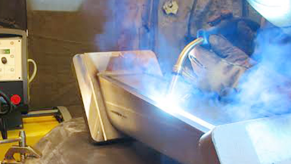
Image by ceaweld
The Core Formulas Used in Every Welding Duty Cycle Calculator
Two equations cover virtually all shop calculations. The first recovers arc-on time from a known rating; the second predicts the new duty cycle when amperage changes.
Basic Arc-On Time Formula
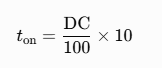
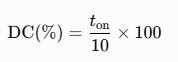
where is minutes of welding and DC is the rated percentage. Reverse the equation to find the duty cycle actually used during a shift:
Amperage-Adjusted Duty Cycle Formula
Because heating follows , duty cycle scales with the square of current:
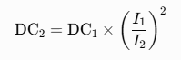
Example: a source rated 60 % at 200 A operated at 250 A yields
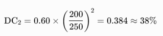
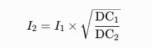
or roughly 3.8 minutes of welding in each 10-minute window. The inverse form finds the maximum current that can be sustained at a desired duty cycle:
Practical Duty Cycle Chart for Common Machine Ratings
| Rated Output | Duty Cycle | Arc-On Time | Cool-Down Time | Typical Process Fit |
|---|---|---|---|---|
| 300 A @ 20 % | 20 % | 2 min | 8 min | Light stick or short MIG repairs |
| 250 A @ 40 % | 40 % | 4 min | 6 min | General fabrication, intermittent MIG |
| 200 A @ 60 % | 60 % | 6 min | 4 min | Structural stick, multi-pass TIG |
| 200 A @ 80 % | 80 % | 8 min | 2 min | Production MIG, pipe welding |
| 350 A @ 100 % | 100 % | 10 min | 0 min | Continuous SAW or robotic GMAW |
| 150 A @ 100 % | 100 % | 10 min | 0 min | Thin-gauge continuous TIG |
These values are representative; always confirm against the specific nameplate.
Matching Duty Cycle to Process and Joint Length
Different processes impose different average arc-on percentages even when the machine rating is identical.
Stick and Manual TIG Constraints
Electrode changes, slag chipping, and position shifts keep real-world duty cycles between 20 % and 35 %. A machine rated only 30 % at the working amperage is usually adequate. Long open-root passes or multi-pass groove welds push the limit; operators must plan deliberate pauses or drop amperage to raise the available percentage.
Semi-Automatic MIG and Flux-Cored Demands
Wire processes routinely achieve 40–60 % arc-on time in production. A 200 A machine rated 60 % at that current supports continuous fillet runs on medium plate without thermal trips. Spray-transfer or pulsed modes at higher currents require either a larger power source or deliberate segmentation of long seams.
Automated and Submerged-Arc Requirements
Robotic cells and SAW systems demand 80–100 % ratings because arc time approaches continuous. Selecting a source whose 100 % current still exceeds the process requirement eliminates cool-down interruptions entirely.
Calculating Usable Current for a Target Duty Cycle on an Existing Machine
When a long continuous weld is required, invert the square-law formula to find the highest amperage that still yields the needed percentage.
Worked Example for a 6-Minute Continuous Pass
A power source is rated 200 A at 60 %. The operator needs 6 minutes of uninterrupted arc (60 % duty). The calculation shows that 200 A is already at the limit. If the joint demands higher current, the only options are a larger machine or splitting the weld into segments with cooling intervals.
Worked Example for Higher Current at Reduced Duty
The same 200 A / 60 % source operated at 250 A drops to approximately 38 %. Maximum continuous time falls to 3.8 minutes. For a 5-minute seam the operator must either lower current, add a mid-pass pause, or accept the risk of thermal shutdown.
Reading Nameplates and Manufacturer Charts Correctly
Nameplates list multiple points: maximum current at low duty cycle and lower currents at higher percentages. Charts or graphs often plot the continuous curve. Always use the values measured at 40 °C; some imported units quote more optimistic figures obtained at cooler ambient temperatures.
Inverter machines typically recover faster than transformer sets because of more efficient cooling and lower internal losses, but the printed percentage remains the binding limit.
Thermal Protection Behavior and Recovery Time
When the internal thermostat opens, output ceases until the temperature falls below the reset threshold. Fans continue to run. Recovery usually takes 5–15 minutes depending on ambient conditions and how far the limit was exceeded.
Repeated trips accelerate capacitor and semiconductor aging. Monitoring the duty cycle with a simple timer prevents the first trip and preserves machine life.
Wrapping Up
Selecting the correct duty-cycle point on the chart or calculator is a direct trade-off between required amperage and uninterrupted arc time. A machine that can deliver the needed current at 60 % or higher for the longest planned continuous pass eliminates mid-weld interruptions and the associated defects.
Advanced operators further improve productivity by scheduling multi-pass sequences so that cooling intervals coincide with slag removal or joint repositioning, effectively raising average arc-on time without increasing the instantaneous thermal load.
FAQs
What does 60% duty cycle mean on a welder?
At the rated amperage it allows 6 minutes of welding followed by 4 minutes of cooling inside every 10-minute window.
How do I calculate duty cycle at a higher amperage than the nameplate rating?
Use . A 60 % rating at 200 A becomes approximately 38 % at 250 A.
Can I run a 40% duty cycle machine continuously by lowering the amps?
Yes. Lowering current raises the available percentage; many machines reach 100 % at roughly 60–70 % of their maximum rated amperage.
Is the 10-minute period the same for all welding processes?
Yes. EN 60974-1 standardizes the thermal test period at 10 minutes regardless of process; only the practical arc-on percentage achieved by the operator changes.


