
Choosing between a groove weld vs fillet weld is more than a matter of weld appearance—it directly affects joint strength, penetration, fabrication time, and inspection requirements.
While both weld types are widely used in structural steel, pipe fabrication, and general metalworking, each is designed for specific joint configurations and load conditions.
Selecting the wrong weld can increase material preparation, raise welding costs, or compromise the performance of the finished assembly.
Understanding the differences between groove and fillet welds helps fabricators, welders, and welding students make informed decisions based on strength requirements, joint design, and applicable welding codes.
By learning where each weld excels and its practical limitations, you can choose the most effective welding method for your project while improving both efficiency and weld quality.
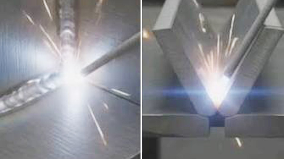
Image by superfast_study_and_experiment
How Joint Geometry Changes Load Transfer
Fillet Weld Cross-Section and Throat Path
A fillet weld deposits a roughly triangular cross-section of weld metal in the corner formed by two surfaces that meet at approximately 90 degrees. The two legs sit against the base metal faces.
The theoretical throat is the shortest distance from the root of the joint to the face of the weld, measured along a line that bisects the angle. For an equal-leg fillet this throat equals 0.707 times the leg size.
Design codes treat the effective throat as that theoretical value, sometimes increased slightly by process penetration. Load is transferred primarily by shear through this throat plane, regardless of whether the external force is tension, compression, or shear.
Groove Weld Cross-Section and Penetration Depth
A groove weld fills a prepared opening between the faying surfaces. The weld metal occupies the space between the prepared edges, so the load path runs through the full depth of the deposited metal rather than a diagonal throat.
In a complete-joint-penetration (CJP) groove weld the effective throat equals the thickness of the thinner member. In a partial-joint-penetration (PJP) groove weld the effective throat is the specified depth of penetration, which is always less than full thickness.
Because the throat is essentially perpendicular to the plate surfaces, the weld can develop nearly the full tensile or compressive capacity of the base metal when matching filler is used.
Why the Geometry Difference Controls Failure Mode
The fillet’s 45-degree throat creates a natural stress concentration at the root and at the weld toes. Fatigue cracks often initiate at these locations under cyclic loading. The groove weld’s more direct load path reduces that geometric stress raiser, provided the root is properly fused and any reinforcement is blended.
This is why structural codes allow CJP groove welds to be treated as equal in strength to the base metal while fillet welds must be sized by calculation of shear on the throat.
Joint Preparation Effort and Its Effect on Cost
Fillet Weld Fit-Up Tolerances
Fillet welds require almost no edge preparation beyond cleaning. The plates or shapes are simply positioned with the correct gap or root contact, clamped, and welded. Fit-up tolerances are generous; a few millimeters of gap can usually be filled by the weld bead itself.
This simplicity keeps labor and equipment time low, which is why fillets dominate light fabrication, frames, brackets, and most field connections.
Groove Weld Edge Preparation Requirements
Groove welds demand deliberate edge preparation. Common preparations include single-V, double-V, single-bevel, double-bevel, U-groove, and J-groove. Typical included angles range from 45° to 60° for V-grooves and 20° to 45° for bevels, depending on process and thickness.
Root openings of 1/16 in to 1/4 in and root faces of 1/16 in to 1/8 in are specified to control penetration and avoid burn-through. Preparation is performed by plasma, oxy-fuel, machining, or grinding.
On thick plate the volume of metal removed and the subsequent filler volume increase rapidly, raising both labor and consumable cost.
When Preparation Cost Is Justified
Once plate thickness exceeds roughly 3/8 in to 1/2 in, the filler volume required for a large fillet often exceeds that of a properly designed PJP or CJP groove. Double-sided grooves further reduce weld metal compared with single-sided preparations.
On high-volume production or critical structural members, the extra preparation time is recovered through reduced welding time, lower distortion, and higher allowable stresses.
Strength Calculation Differences That Drive Design
Fillet Weld Strength Formula
AWS D1.1 and AISC treat fillet strength as shear rupture on the effective throat. Nominal strength per unit length is 0.60 × FEXX × 0.707 × leg size (or the measured throat). A resistance factor of 0.75 is applied for LRFD.
Directional strength increase is permitted when the load is transverse to the weld axis, raising the allowable by up to 50 percent. Minimum leg sizes are governed by the thicker member to ensure proper fusion and heat input.
Groove Weld Strength Rules
For CJP groove welds made with matching filler metal, the joint strength is taken as equal to the base-metal strength; no separate weld calculation is required. For PJP groove welds the effective throat is the depth of preparation minus any required deduction (commonly 1/8 in for certain processes and details).
Strength is then calculated on that throat using the same 0.60 FEXX shear value or the base-metal tensile value, whichever governs.
Adding a reinforcing fillet to a PJP does not simply add the two throats; the combined effective throat is measured from the root to the outermost face, with the code-prescribed deduction still applied.
Practical Comparison of Throat Efficiency
A 5/16-in equal-leg fillet has a theoretical throat of approximately 0.22 in. A PJP groove with 3/8-in preparation depth can deliver a larger effective throat with less deposited metal once the geometry is optimized.
On thicker material the advantage of the groove becomes decisive because fillet size grows linearly with required capacity while groove throat can approach full plate thickness.
Situations Where One Weld Type Clearly Outperforms the Other
Applications That Favor Fillet Welds
Fillet welds excel on T-joints, lap joints, and corner joints where the members already form a natural angle. They are the default for secondary members, stiffeners, connection plates, and most shop fabrication under static loads.
When access is limited to one side and full penetration is unnecessary, a fillet (or double fillet) is faster and cheaper. Field welding of structural steel relies heavily on fillets because scaffolding and joint access rarely allow the precise fit-up needed for groove welds.
Applications That Demand Groove Welds
CJP groove welds are required when the joint must develop the full tensile capacity of the member—column splices, moment connections, pressure-vessel longitudinal seams, and many pipe butt joints. PJP grooves are used when partial strength is acceptable but a fillet of equivalent capacity would be excessively large.
Cyclic or fatigue-critical details often specify groove welds with ground toes or smooth transitions to eliminate the geometric stress concentration inherent in fillets.
Hybrid Solutions That Combine Both
A common high-performance detail is a PJP groove reinforced with a fillet. The groove provides the primary throat while the fillet improves the stress distribution at the re-entrant corner and adds a small amount of additional capacity.
Codes allow this combination provided the effective throat is calculated correctly and the fillet does not create an undercut or excessive convexity.
Process and Parameter Adjustments Required by Each Weld Type
Travel Speed, Amperage, and Heat Input for Fillets
Fillet welds are typically run at moderate to high travel speeds to control leg size and avoid excessive convexity. For GMAW short-circuit or spray transfer on 1/4-in to 3/8-in legs, wire feed speeds of 250–400 ipm and voltages of 22–28 V are common.
Vertical-up fillets require lower heat and a triangular weave or stringer technique to prevent sagging. The goal is consistent leg length and a flat to slightly convex face without undercut at the toes.
Root Pass and Fill Sequence for Groove Welds
Groove welds begin with a carefully controlled root pass. Open-root joints often use GTAW or specialized GMAW root techniques with reduced amperage and tight gap control. Subsequent fill passes can use higher deposition rates—spray transfer, pulsed GMAW, or FCAW—because the groove walls support the puddle.
Interpass temperature limits become critical on thicker sections to avoid excessive grain growth or hydrogen cracking. Double-sided grooves require back-gouging or grinding to sound metal before the second side is welded.
Distortion Control Differences
Fillet welds on one side of a T-joint produce angular distortion that is difficult to correct after the fact. Balanced double fillets or sequenced welding reduce the problem. Groove welds, especially single-V on thick plate, generate more transverse shrinkage; double-V or U-groove preparations with balanced welding from both sides minimize bowing and residual stress.
Inspection Criteria and Acceptance Limits
Visual and NDT Expectations for Fillet Welds
Most fillet welds are accepted by visual inspection for leg size, profile, undercut, and porosity. Magnetic-particle or liquid-penetrant testing is added for critical members. Ultrasonic testing is less common because the geometry makes interpretation difficult. Acceptance is based on the minimum throat and the absence of cracks or incomplete fusion at the root.
Higher Scrutiny Applied to Groove Welds
CJP groove welds frequently require ultrasonic or radiographic examination to verify complete penetration and the absence of lack of fusion, slag, or porosity throughout the throat. PJP welds are inspected to confirm the specified penetration depth.
Because the strength claim of a CJP weld rests on full continuity, the inspection burden and the cost of repair are higher than for fillets.
Decision Framework for Selecting the Correct Weld
Load Type and Magnitude as the First Filter
Static shear or light tension on secondary members points to fillets. Full tension, moment, or fatigue loading on primary members points to CJP grooves. Intermediate cases are evaluated by calculating the required throat and comparing the volume of weld metal and preparation cost.
Access, Thickness, and Production Volume
One-sided access and thin material favor fillets. Two-sided access and thickness above ½ in often favor grooves. High-volume production justifies the capital cost of edge-preparation equipment when the per-joint welding time drops.
Code and Drawing Requirements
Always verify the governing code (AWS D1.1, D1.6, ASME Section IX, etc.) and the weld symbols on the drawing. A CJP symbol with no size means full penetration is mandatory. A fillet symbol with a leg size is a direct instruction. When the drawing is silent, the engineer or welding supervisor must decide based on the load path and economy.
Wrapping Up
Choosing correctly between groove weld and fillet weld comes down to matching the effective throat and load path to the actual forces while minimizing preparation and filler volume.
On any given joint, calculate the required throat first, then compare the total cost of edge preparation plus welding time for each option.
The advanced insight is that many “full-penetration” call-outs on drawings are over-specified; a properly sized PJP groove with a reinforcing fillet often delivers the needed capacity at substantially lower cost and residual stress while still satisfying code requirements for static structures.
FAQ
What is the main strength difference between a groove weld and a fillet weld?
A CJP groove weld can develop the full tensile strength of the base metal. A fillet weld is limited to shear strength on its effective throat (0.707 × leg size), so it requires a larger deposited cross-section to carry the same tensile load.
Can a fillet weld ever replace a groove weld on thick plate?
Only if the required capacity can be met with a practical fillet size and the joint geometry allows it. Once the calculated fillet leg exceeds about ½ in to ⅝ in, a PJP or CJP groove usually becomes more economical and produces less distortion.
Why do codes treat CJP groove welds as equal to the base metal?
Because the effective throat equals the full thickness of the thinner member and matching filler metal is used, the joint is as strong as the continuous plate. No separate weld-metal calculation is needed.
Is joint preparation always required for a groove weld?
Yes. Even a square-groove weld on thin material requires a controlled root opening. Beveled or U-groove preparations are mandatory on thicker sections to achieve the specified penetration and to control the weld-metal volume.


