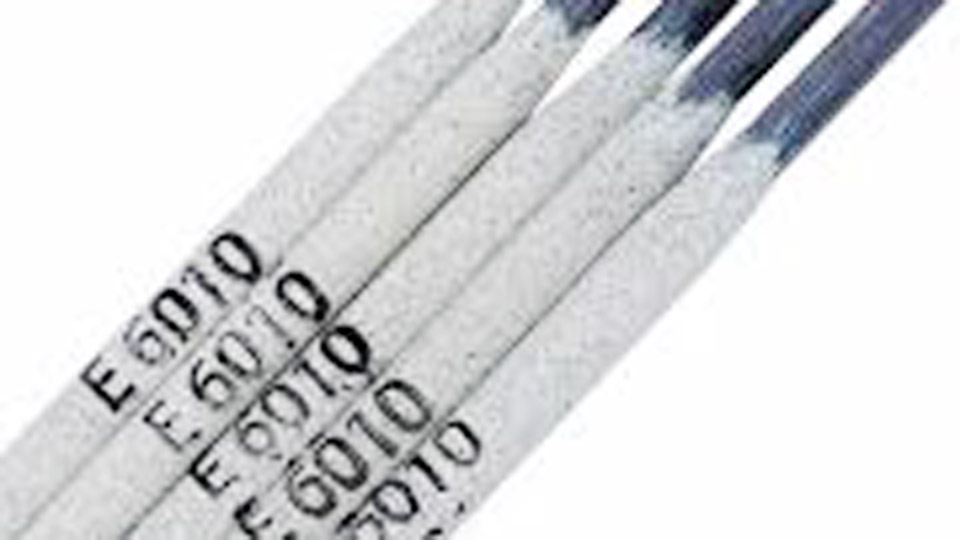
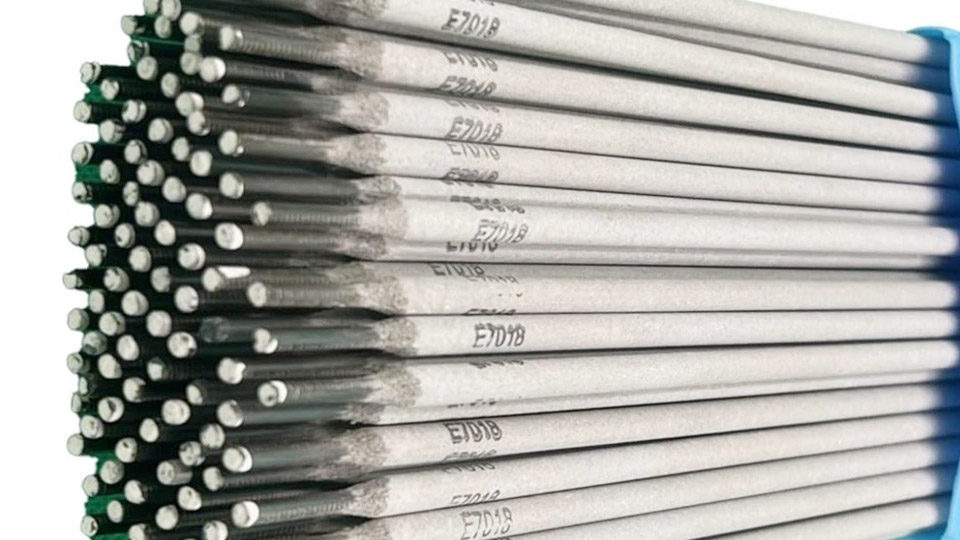
A low-cost portable stick welder is often needed for thin sheet, farm repairs, or practice when commercial 110 V inverters exceed budget or lack the exact duty-cycle profile required.
Understanding how to make small welding machine at home centers on converting a step-down transformer into a high-current, low-voltage AC source capable of sustaining an arc with 1/16″ to 3/32″ electrodes.
The critical parameters are open-circuit voltage (typically 25–40 V), short-circuit current (50–150 A), and thermal mass that determines usable duty cycle.
Incorrect secondary turns or inadequate cooling produce either an unstable arc that will not maintain or rapid core saturation that trips breakers and overheats insulation within minutes.
Matching core size, wire gauge, and input voltage to the intended electrode diameter and material thickness determines whether the finished unit delivers usable welds or simply becomes a short-lived experiment.
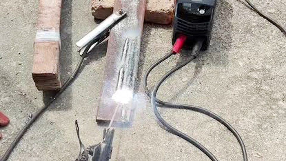
Image by @kelseyivan0
Core Electrical Requirements for a Functional Small Stick Welder
A usable arc requires enough open-circuit voltage to ionize the gap and enough current to maintain the molten pool without excessive voltage drop under load.
Open-Circuit Voltage and Arc Stability Targets
Most 6013 and 6011 electrodes in the 1/16″–3/32″ range strike and hold reliably between 25 V and 40 V AC open circuit. Below 22 V the arc extinguishes on any slight increase in arc length; above 50 V the risk of shock rises and the machine becomes harder to control on thin material.
Measured open-circuit voltage after winding should sit near 30–35 V when the primary is energized at the intended line voltage.
This range also keeps the no-load current of a typical microwave-oven-transformer (MOT) core within manageable limits before magnetic shunts or series-parallel switching are added.
Current Capacity and Duty Cycle Realities
A single large MOT core can support roughly 50–90 A continuous before temperature rise exceeds safe insulation ratings. Two matched cores connected with secondaries in series raise voltage while paralleling primaries or secondaries increases available current toward 120–150 A.
Real duty cycle on these builds rarely exceeds 30–40 % at the higher current settings because the laminated cores and secondary conductors heat rapidly.
At 60–80 A the same cores often sustain 60–70 % duty cycle if forced-air cooling is present. Exceeding these thermal limits softens the varnish, increases primary current draw, and eventually fails the insulation.
Transformer Selection and Secondary Winding Decisions
The transformer is the entire power source. Core cross-section and window area set the maximum continuous power; secondary turns and wire cross-section set voltage and current.
Microwave Oven Transformer Characteristics
An 800–1200 W microwave transformer contains a heavy laminated core sized for intermittent high-voltage, low-current service. Removing the original high-voltage secondary leaves the primary intact (typically 100–150 turns of moderate gauge wire for 120 V or 200–300 turns for 240 V).
The remaining window area determines how many turns of heavy welding cable can be installed. Larger cores from 1000 W+ ovens accept 14–20 turns of 6 AWG or 8 AWG cable more easily and run cooler under load.
Magnetic shunts, if present, can be left in place for better current regulation or removed to raise maximum current at the expense of higher no-load draw.
Secondary Turns, Gauge, and Series-Parallel Arrangements
Fourteen to eighteen turns of 6 AWG or 8 AWG stranded welding cable on each core commonly produce 28–38 V open circuit when the primary is supplied at design voltage. Fewer turns raise current capability but drop open-circuit voltage below the reliable striking range; more turns raise voltage while reducing available amperage.
Two identical cores with secondaries wired in series add the voltages for easier arc starts; primaries may be paralleled for 120 V operation or left separate for 240 V.
Parallel secondary connection increases current but halves voltage, so most practical builds keep secondaries in series and control current by primary configuration or external resistance.
Input Power, Current Control, and Thermal Management
Line voltage, cable size, and cooling dictate both performance and survival of the machine.
120 V versus 240 V Supply Trade-offs
A single MOT on 120 V draws high primary current and saturates quickly under load. Two cores on 240 V (split-phase) distribute the load, reduce primary amperage per leg, and allow higher secondary output before breaker trip.
Primary cable should be 10 AWG minimum for 120 V builds and 8 AWG or heavier for 240 V. A properly rated switch or contactor on the primary side is required; ordinary light switches fail under the inductive load.
Amperage Control Methods and Heat Dissipation
Series-parallel primary switching provides two or three discrete current ranges. External series reactors or lengths of steel cable can further limit current for thin material. Continuous forced-air cooling across the cores and secondary windings is mandatory; without it the duty cycle collapses to a few minutes.
Temperature rise on the secondary insulation should be monitored during initial tests—surface temperatures above 100–120 °C indicate the need for reduced current or longer rest periods.
Expected Performance on Common Electrodes and Thicknesses
| Material Thickness | Electrode | Approximate Current Range | Typical Duty Cycle on Dual-MOT Build |
|---|---|---|---|
| 20–16 ga sheet | 6013 1/16″ | 40–70 A | 70–90 % |
| 1/8″ plate | 6013 3/32″ | 70–100 A | 50–70 % |
| 3/16″–1/4″ | 6013 or 7018 3/32″–1/8″ | 90–140 A | 25–40 % |
Arc starts are easier with cellulose or rutile rods (6010/6011/6013) than with low-hydrogen 7018 because the latter prefers higher open-circuit voltage and smoother current delivery than most MOT builds provide. Penetration on 1/4″ material is marginal; multiple passes and careful joint preparation become necessary.
Practical Limits and Safer Alternatives
Homemade transformer machines excel at intermittent light-gauge work and practice but lack the constant-current characteristic, arc force control, and thermal protection of commercial inverters.
Grounding of the chassis, proper insulation of all primary connections, and residual-current protection on the supply circuit are non-negotiable.
Battery-based or capacitor-discharge spot welders serve a different purpose (tab welding) and do not replace an arc machine. Ready-made 110 V inverter welders in the 80–140 A class now cost little more than the scavenged parts plus safe enclosure and cables, while offering better duty cycle, DC output options, and built-in protection.
Wrapping Up
Choosing a dual-MOT AC design makes sense only when the builder already possesses the cores, understands inductive loads and insulation ratings, and accepts a limited duty cycle for thin-to-medium work.
For consistent results on 1/8″ and thicker material, or for any work requiring low-hydrogen electrodes, a commercial constant-current inverter remains the higher-performance and lower-risk decision.
Advanced users further improve arc stability by adding a small series inductor on the secondary and verifying every joint with a calibrated clamp meter under short-circuit conditions before any welding begins.
FAQs
What open-circuit voltage is needed for a homemade stick welder?
25–40 V AC is the practical window. Most dual-MOT builds target 30–35 V for reliable starts with 1/16″ and 3/32″ 6013 electrodes.
How many amps can a dual microwave transformer welder deliver?
50–150 A depending on secondary turns, wire gauge, and whether the cores run in series or parallel configuration. Sustainable output is usually limited by heat to the lower half of that range.
Can a homemade MOT welder run 7018 electrodes?
Marginally at best. Low-hydrogen rods prefer higher open-circuit voltage and smoother DC or well-regulated AC; most MOT builds perform better with 6013 or 6011 rods.
Is 120 V or 240 V better for a small homemade welder?
240 V reduces primary current draw, improves duty cycle, and allows higher secondary output before the supply circuit limits performance.