Choosing the Best Setting for 7018 Welding Rod is one of the most important factors in producing strong, defect-free welds. Even a high-quality low-hydrogen electrode can deliver poor results if the amperage, polarity, or arc length is incorrect.
Settings that are too low often cause lack of fusion and unstable arcs, while excessive current can increase spatter, undercut, and overheating. These issues lead to wasted electrodes, additional grinding, costly rework, and welds that may fail inspection or service requirements.
Because 7018 electrodes are widely used for structural steel, pressure applications, and critical fabrication, proper machine setup directly affects weld quality, penetration, and overall productivity.
Understanding the correct settings for different rod diameters, material thicknesses, and welding positions allows you to achieve a stable arc, consistent bead appearance, and reliable mechanical performance under real welding conditions.
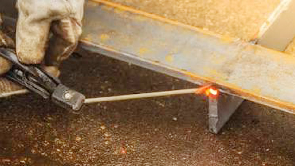
Image by simpleweld
Understanding 7018 Electrode Characteristics
AWS Classification and Mechanical Properties
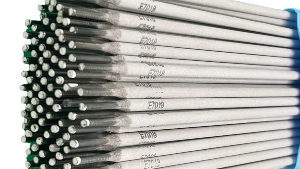
E7018 electrodes produce welds with a minimum tensile strength of 70,000 psi, good ductility, and superior impact resistance at low temperatures. The “8” indicates low-hydrogen potassium coating with iron powder, enabling all-position welding on AC or DCEP.
This flux minimizes diffusible hydrogen, making 7018 ideal for pressure vessels, bridges, heavy equipment, and code work where crack resistance matters.
The iron powder in the coating increases deposition rates compared to non-iron powder low-hydrogen rods while maintaining a smooth, stable arc. Expect a medium to deep penetrating arc with easy slag release and minimal spatter when settings are optimized.
When to Choose 7018 Over Other Rods
Select 7018 for applications demanding high strength and low hydrogen: structural fabrication, pipe welding (fill and cap passes), repair of thick sections, or dynamic load-bearing joints. It outperforms 6013 in strength and toughness but requires stricter storage and slightly more skill for out-of-position work.
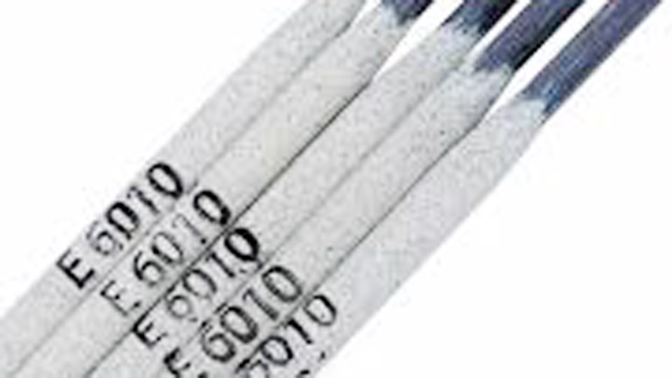
Compared to 6010/6011, 7018 offers quieter arcs, less spatter, and better mechanical properties for non-root passes. Use 7018 when weld quality and long-term integrity outweigh the need for deep penetration or fast-freezing slag.
Optimal Amperage Settings by Electrode Diameter
Recommended Ranges and Starting Points
Amperage is the most critical variable for 7018 performance. Manufacturer charts provide baselines, but real-world adjustments account for joint type, position, and base metal thickness.
| Electrode Diameter | Flat/Horizontal Amps | Vertical/Overhead Amps | Typical Material Thickness |
|---|---|---|---|
| 3/32″ (2.4 mm) | 70–110 | 65–95 | Up to 1/4″ |
| 1/8″ (3.2 mm) | 90–150 | 85–130 | 1/4″–3/8″ |
| 5/32″ (4.0 mm) | 140–220 | 130–190 | 3/8″–1/2″+ |
| 3/16″ (4.8 mm) | 180–280 | 170–240 | 1/2″ and thicker |
A common rule of thumb: start near the decimal equivalent of the rod diameter in amps (e.g., ~125A for 1/8″) and fine-tune. Higher settings suit flat positions and thicker material; lower settings prevent puddle runoff in vertical or overhead.
Adjusting Amps for Joint and Position
For fillet welds on 1/4″ plate, 1/8″ 7018 often runs best at 110–130A in flat position. On thicker plate or multi-pass grooves, increase toward the upper range for better penetration without excessive heat input.
Vertical uphill typically requires 10–20A less than flat to control the puddle. Overhead demands the tightest control—drop amps further and shorten arc length to fight gravity.
Test on scrap: if the arc sounds harsh or the puddle is too fluid, reduce amperage. If the rod sticks or penetration is shallow, increase it slightly. Modern inverter machines with adjustable arc force (dig) help stabilize the arc at lower settings—set arc force moderate to high for 7018.
Polarity and Machine Setup
Preferred Polarity: DCEP (Reverse Polarity)
7018 performs best on Direct Current Electrode Positive (DCEP). This concentrates heat at the workpiece for optimal penetration and puddle control while the electrode receives less heat, reducing coating breakdown.
Most procedures specify DCEP; AC works on some machines and 7018-AC variants but often yields a less stable arc. Avoid DCEN except in rare root pass scenarios.
Set polarity correctly on your machine and verify with a test arc. Incorrect polarity produces a wandering arc, poor fusion, and excessive spatter.
Voltage, Arc Force, and Hot Start
7018 typically runs at 20–28V depending on diameter and technique. Maintain a short arc length—nearly dragging the coating on the workpiece. Many inverters include hot start (increase initial current briefly to prevent sticking) and arc force controls. Moderate hot start and arc force around 20–40% improve starts with 7018.
Techniques for Consistent Welds
Arc Length and Travel Speed
Keep the arc extremely short—about 1/16″ or less, often described as a drag technique. Longer arcs introduce porosity and undercut because the protective gas shield weakens.
Travel speed should allow the puddle to build slightly ahead of the electrode without flooding the joint. In flat position, a steady drag produces stacked dimes appearance with minimal weaving.
Bead Patterns and Weaving
Stringer beads work well in flat and horizontal positions for efficiency and low heat input. For vertical uphill, use controlled weaves: a slight side-to-side motion or “Christmas tree” pattern, pausing at the toes to tie in and prevent undercut.
Limit weave width to 2–3 times the core wire diameter to avoid slag inclusions. Overlap passes by at least 50% in multi-pass welds.
In overhead, maintain a tight arc and slightly faster travel speed. Rod angle of 10–15° push (leading angle) helps direct the puddle and shield.
Handling Different Positions
- Flat/Horizontal: Highest amperage range, drag technique, minimal weave.
- Vertical Uphill: Reduced amperage, tighter control, weave or whip as needed.
- Overhead: Lowest practical amperage, shortest arc, steady hand positioning for comfort.
Practice padding beads in each position to develop muscle memory before production welds.
Material Thickness and Joint Preparation
Matching Settings to Thickness
For thin material (<1/4″), use 3/32″ rods at lower amperage to avoid burn-through. On 3/8″–1/2″ plate, 1/8″ or 5/32″ provides good deposition. Thicker sections benefit from larger diameters and multi-pass techniques with interpass temperatures controlled (typically under 350°F for low-alloy steels) to manage heat input and prevent distortion.
Clean mill scale, rust, and contaminants thoroughly before welding. 7018 is less forgiving of dirty metal than rutile rods. Bevel joints appropriately for full penetration.
Multi-Pass Welding Strategy
Root passes may use slightly higher amperage for penetration, followed by fill and cap passes at balanced settings. Remove slag completely between passes—7018 slag chips easily but must be cleaned to avoid inclusions. Maintain consistent interpass cleaning and temperature.
Storage, Handling, and Maintenance
Proper Storage Practices
Low-hydrogen coatings absorb moisture rapidly, leading to porosity or cracking. Store unopened packages in cool, dry conditions. Once opened, keep rods in a holding oven at 250–300°F. For hobbyists, sealed containers with desiccant work for short-term storage.
Reconditioning Wet Rods
If rods absorb moisture, re-dry at 500–800°F for 1–2 hours depending on severity and manufacturer guidelines. Avoid home ovens due to fire risk and imprecise temperatures. Limit re-drying cycles—electrodes have a finite number of reconditioning cycles before performance degrades.
Discard rods that show heavy rust or damaged coatings.
Common Setting Challenges and Solutions
Porosity and Undercut
Porosity often traces to moisture, long arc length, or dirty metal. Undercut results from excessive amperage, fast travel, or improper angle. Solutions: shorten arc, clean base metal, adjust amperage down slightly, and ensure proper rod angle (5–15°).
Arc Stability and Sticking
Low amperage or cold starts cause sticking. Use hot start and increase dig/arc force. For thin material or out-of-position, step down one rod size.
Heat Input Control
Calculate approximate heat input (Amps × Volts × 60 / Travel Speed in ipm) for code jobs. 7018 tolerates moderate heat but excessive input reduces toughness.
Advanced Considerations for Professional Results
For critical applications, monitor diffusible hydrogen levels and follow qualified WPS (Welding Procedure Specifications). Preheat thick or high-carbon steels, control interpass temperature, and post-weld heat treat when specified. Combine 7018 with proper joint design and fit-up for optimal performance.
In high-productivity shops, consider iron powder variants or mechanized setups, but core manual techniques remain essential.
Performance-Based Takeaway
Mastering the best setting for 7018 welding rod—primarily 90–150A for 1/8″ on DCEP with a short drag arc—transforms it into a reliable workhorse for strong, defect-free welds across positions. The key decision is balancing amperage, arc length, and travel speed to the specific joint while respecting storage requirements.
Experienced welders achieve x-ray quality by treating 7018 parameters as a precise system rather than guesswork, delivering welds that meet both code and real-world durability demands.
One pro-level insight: in vertical multi-pass work, slight variations in weave timing and overlap often separate acceptable welds from code-perfect ones—focus on puddle control over raw deposition speed.
FAQ
What is the best amperage for 1/8″ 7018 rod?
90–150A on DCEP for most applications. Start at 110–130A in flat position and adjust down 10–20A for vertical/overhead or thinner material.
Can 7018 be run on AC?
Yes, many 7018 rods and machines support AC, but DCEP usually provides better arc stability and penetration. Use manufacturer-rated AC settings if DC is unavailable.
How do you prevent porosity with 7018?
Maintain very short arc length, ensure dry rods via proper storage or re-drying, and thoroughly clean the joint. Avoid drafts that disrupt shielding.
What rod size for welding 1/2″ thick steel?
5/32″ or 3/16″ 7018 at 160–250A+ depending on position and passes. Use multi-pass technique with 1/8″ for root if needed for better control.