Choosing the correct welding rod diameter is one of the most important decisions for producing strong, reliable welds. How to choose welding rod size depends on several factors, including base metal thickness, joint design, welding position, and the available amperage.
Using a rod that is too large can cause poor fusion and excessive heat input, while one that is too small may reduce penetration, increase deposition time, and compromise weld quality. Incorrect rod selection can also lead to arc instability, excessive spatter, distortion, failed inspections, and costly rework.
Understanding how rod size affects welding performance helps you match the electrode to the job instead of relying on guesswork. With the right approach, you can improve weld consistency, control heat input more effectively, and produce cleaner, stronger welds across a wide range of fabrication and repair applications.
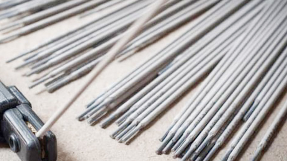
Image by arccaptain
Understanding Common Welding Rod Diameters
Welding electrodes for stick welding range from 1/16″ (1.6 mm) to 1/4″ (6.4 mm) or larger in industrial applications. Each size delivers specific current-carrying capacity, deposition rates, and suitability for base metal thicknesses.
Standard Diameters and Their Primary Applications
- 1/16″ (1.6 mm): Ideal for thin sheet metal under 1/8″ (3 mm). Low heat input prevents distortion and burn-through on light fabrication or auto body work. Typical amperage: 20-60 A.
- 3/32″ (2.4 mm): Versatile for materials from 1/8″ to 1/4″ (3-6 mm). Balances control and penetration for general repairs and light structural work.
- 1/8″ (3.2 mm): Most common general-purpose size for 1/4″ to 1/2″ (6-12 mm) plate. Offers good deposition without overwhelming smaller machines.
- 5/32″ (4.0 mm): Suited for heavier sections 3/8″ to 3/4″ (10-19 mm). Higher deposition speeds up multi-pass welds on structural steel.
- 3/16″ (4.8 mm) and larger: Reserved for thick plates over 1/2″ (12 mm), heavy fabrication, and high-deposition needs. Requires machines with sufficient output (200+ A).
Larger diameters increase deposition rate proportionally but demand higher amperage and skill to maintain arc stability.
Diameter-to-Thickness Matching Principles
The electrode diameter should generally approximate 1/2 to 3/4 of the base metal thickness for single-pass welds, or match it closely in multi-pass scenarios. For a 1/4″ plate, a 3/32″ or 1/8″ rod provides optimal control. Exceeding base metal thickness risks excessive heat and distortion.
In practice, test on scrap: run a bead and section it to verify penetration and fusion. Adjust based on observed results rather than rigid formulas.
Key Factors in Welding Rod Size Selection
Multiple variables interact when selecting size. Prioritize material thickness first, then refine with position, joint type, and power source limits.
Base Metal Thickness and Heat Management
Thickness dictates minimum heat input for fusion. Thin materials (<1/8″) require smaller rods to limit heat-affected zone (HAZ) expansion and warping. Thicker materials need larger rods for adequate penetration without excessive passes.
For example:
- 16-gauge sheet (~1.5 mm): 1/16″ rod at 30-50 A.
- 1/4″ plate: 1/8″ rod at 90-140 A.
- 1/2″ plate: 5/32″ or 3/16″ rod at 140-200+ A.
Account for heat sink effects—thicker or colder plates dissipate heat faster, often requiring amperage toward the upper end of the range.
Welding Position and Arc Control
Position significantly affects puddle fluidity and size choice.
Flat/Horizontal: Larger rods (1/8″–5/32″) maximize deposition and speed. Gravity assists puddle control.
Vertical Up: Smaller diameters (3/32″–1/8″) create manageable puddles. Larger rods risk slag inclusion or undercut due to gravity pulling molten metal downward.
Overhead: Prioritize 3/32″ or smaller for short arcs and quick freeze times. Higher skill compensates for larger sizes, but productivity drops.
Vertical Down: Fast-freezing electrodes like 6010/6011 in 1/8″ allow quicker travel on thinner sections.
Joint Design and Fit-Up Considerations
Root passes in open V-grooves or pipe welds often use smaller rods (3/32″) for precise control and full penetration. Fill and cap passes permit larger sizes for efficiency. Poor fit-up (gaps) favors smaller rods to bridge without excessive filler or burn-through.
Matching Rod Size to Common Electrode Types
Electrode classification influences size viability due to coating thickness, flux behavior, and current requirements.
Cellulosic Electrodes (E6010, E6011)
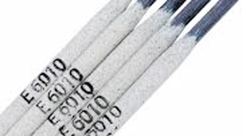
These deep-penetrating rods suit root passes and dirty metal. 1/8″ is standard for most pipeline and repair work. E6010 prefers DC+; E6011 runs well on AC. Smaller sizes (3/32″) excel on thin wall pipe to avoid keyholing.
Amperage example for 1/8″ E6010: 75-125 A, adjusted by position and thickness.
Rutile Electrodes (E6013)
Easy-arc, shallow-to-medium penetration for sheet metal and repairs. Use 3/32″ for light work and 1/8″ for general fabrication. They tolerate slight amperage variations well, making them forgiving for hobbyists.
Low-Hydrogen Electrodes (E7018)
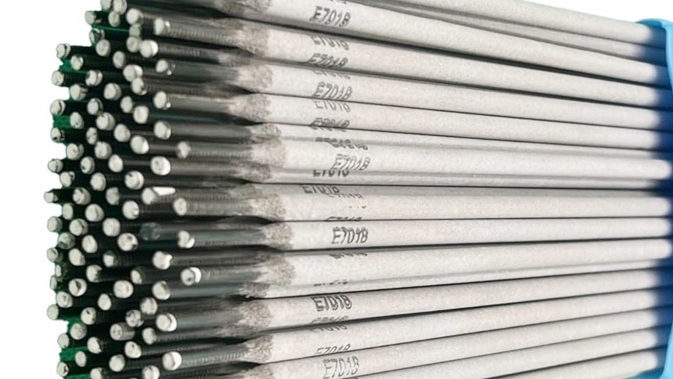
Structural favorites for high-strength welds. Moisture control is critical. 1/8″ handles most structural steel up to 1/2″. Larger 5/32″ boosts productivity on thick sections but requires preheating and interpass temperature control on high-carbon steels to prevent cracking.
Iron Powder Electrodes (E7014, E7024)
Higher deposition rates suit flat/horizontal positions. Larger diameters perform best here, as the thick coating supports higher currents without instability.
Amperage Settings and Machine Compatibility
Rod size and amperage are inseparable. A common rule of thumb: 1 amp per 0.001″ of electrode diameter (e.g., 1/8″ ≈ 125 A starting point), then fine-tune.
Typical Amperage Ranges by Size
Use manufacturer data as baseline and adjust ±10-20 A based on technique and conditions:
- 1/16″: 20-60 A
- 3/32″: 40-100 A
- 1/8″: 75-150 A
- 5/32″: 110-200 A
- 3/16″: 150-250 A
Lower amperage for vertical/overhead or thin material. Higher for flat position or thick plate. Monitor for signs: too low causes sticking and poor fusion; too high produces undercut, porosity, or spatter.
Machine output limits selection. A 140 A welder comfortably runs up to 1/8″ rods; larger projects need 200+ A machines.
Advanced Considerations for Specific Applications
Pipe and Pressure Vessel Welding
Root pass typically uses 3/32″ or 1/8″ E6010 for keyhole technique and full penetration. Hot pass and fills move to 1/8″ or 5/32″ E7018. Diameter consistency across passes maintains uniform bead profile.
Structural Steel Fabrication
Favor 1/8″–5/32″ E7018 for multi-pass fillet and groove welds. Calculate required tensile strength (e.g., 70 ksi for 7018) and match to base metal. Larger rods reduce total passes, lowering labor and distortion risk.
Repair and Maintenance Work
Variable conditions often call for 3/32″ or 1/8″ E6011 for tolerance to rust, paint, or gaps. Test small beads first to dial in settings on unknown material.
Multi-Pass Welding Strategy
Start with smaller rod for root to ensure fusion, then step up sizes for subsequent passes. This optimizes penetration and fill efficiency while controlling overall heat input.
Performance Impacts of Rod Size Choices
Larger rods increase deposition rate (lbs/hour) but raise heat input, potentially affecting microstructure and toughness in heat-sensitive alloys. Smaller rods offer precision but lower productivity.
Track travel speed: larger rods support faster speeds in flat position, improving economy. In constrained positions, smaller rods maintain quality at the cost of time.
For critical applications, qualify procedures per AWS D1.1 or ASME codes, documenting size, amperage, and travel parameters.
Decision-Making Framework for Welding Rod Size
Evaluate in this order: thickness → position → electrode type → machine capability → joint requirements. Cross-reference with amperage charts and test welds. Consistent documentation of successful combinations builds shop-specific knowledge faster than generic charts alone.
Prioritize fusion and mechanical properties over speed initially. With experience, optimize for productivity without compromising integrity.
Real-world Application Insight
On a recent heavy equipment repair involving 3/4″ thick high-strength steel, switching from 1/8″ to 5/32″ E7018 in flat position reduced passes from six to four per joint while maintaining Charpy impact values above specification. The key was balancing higher deposition with precise interpass temperatures.
Pro-level welders master this interplay of size, heat, and sequence for repeatable excellence across diverse projects.