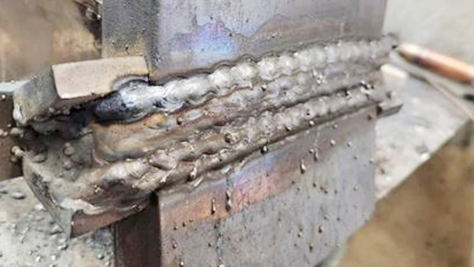
Burning a hole through 20-gauge sheet or watching a panel warp after one continuous bead is the most common failure when trying how to weld thin metal with flux core.
Self-shielded flux-cored wire runs hotter and deposits more metal than solid MIG wire of the same diameter, so the heat input quickly exceeds the capacity of material under 1/8 inch.
The difference between a sound joint and scrap is precise control of voltage, wire feed speed, polarity, travel speed, and bead length.
Mastering these variables lets DIY welders, hobbyists, and professionals join 22-gauge to 16-gauge mild steel outdoors or on dirty surfaces without gas, while still producing functional, low-distortion welds.
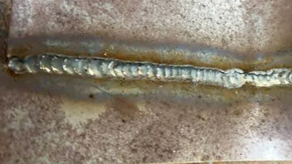
Image by fb/I See You Don’t Know Shit About Welding
Choosing the Right Flux-Core Wire Diameter for Thin Gauge Steel
Wire diameter controls both deposition rate and minimum usable amperage. On thin stock the wrong size forces either excessive heat or an unstable arc.
Why 0.030-Inch Wire Outperforms 0.035-Inch on Sheet Metal
0.030-inch E71T-11 or E71T-GS wire melts at lower amperage and produces a smaller puddle. It is rated for single-pass work from roughly 22 gauge to 14 gauge.
The reduced cross-section limits heat input, giving the operator more time to travel before burn-through occurs. Most 120-volt machines feed 0.030-inch wire cleanly at the low end of their range.
When 0.035-Inch Wire Becomes Practical
0.035-inch wire can be used on 16-gauge and thicker material once voltage and wire speed are lowered to the bottom of the manufacturer’s chart. On anything thinner it deposits too much metal too quickly, raising the risk of undercut and warpage.
Reserve it for overlapping thicker sections or when higher deposition is required after the first tack sequence.
Machine Settings That Keep Heat Input Manageable
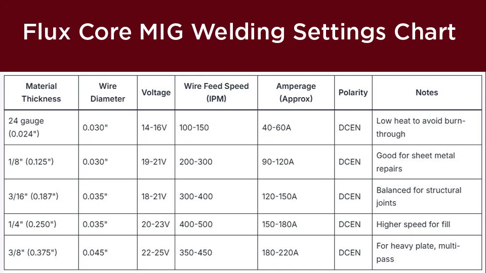
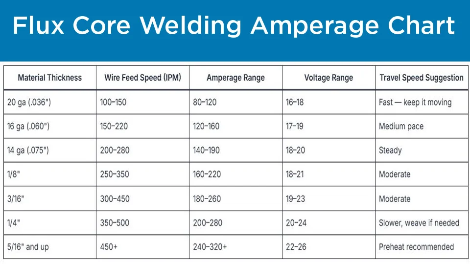
Voltage sets arc length; wire feed speed sets amperage. Both must stay at the low end of the range for thin metal.
Recommended Starting Parameters by Gauge
| Metal Thickness | Wire Diameter | Voltage | Wire Feed Speed (IPM) | Approx. Amps | Travel Speed |
|---|---|---|---|---|---|
| 22–24 gauge | 0.030″ | 14–16 V | 90–140 | 50–70 | Fast (10–15 ipm) |
| 20 gauge | 0.030″ | 15–17 V | 110–160 | 60–90 | Medium-fast (8–12 ipm) |
| 18 gauge | 0.030″ | 16–18 V | 130–180 | 70–100 | Medium (7–10 ipm) |
| 16 gauge | 0.030″ or 0.035″ | 17–19 V | 150–220 | 90–120 | Medium (6–9 ipm) |
These values assume DCEN polarity, clean mild steel, and a ⅜- to ½-inch contact-tip-to-work distance. Always verify against the wire data sheet and the chart inside the machine door, then refine on scrap of identical thickness.
Polarity and Stick-Out Decisions
Self-shielded flux-core wire requires DC electrode negative (DCEN). This places more heat in the wire and less in the base metal—exactly the opposite of solid-wire MIG.
Stick-out of ⅜ to ½ inch keeps the arc short and focused; longer stick-out softens the arc and increases spatter, while shorter stick-out raises heat and risks burn-back into the tip.
Joint Fit-Up and Heat-Management Techniques That Prevent Burn-Through
Even perfect settings fail if the joint allows the arc to dwell or if heat cannot escape.
Tight Fit-Up Versus Bridging Gaps
Gaps larger than 1/16 inch force the operator to slow travel or increase voltage to fill, both of which raise heat input.
Grind edges square, clamp firmly, and use a copper or aluminum backing bar behind open root or edge joints. The backing acts as a heat sink and supports the puddle so the arc does not punch through.
Stitch Welding and Skip Sequences
Continuous beads longer than ¾–1 inch on 20-gauge or thinner material almost always warp or burn through. Instead, place ½-inch stitches spaced 1–2 inches apart, then move to a distant section of the joint.
Allow the metal to cool to warm-to-the-touch before returning. This distributes heat and keeps residual stress low.
Gun Angle, Travel Direction, and Puddle Control on Thin Stock
Technique determines whether the available heat stays in the joint or overheats the surrounding sheet.
Drag Angle and Work Angle for Self-Shielded Wire
A 5–15° drag (pull) angle is standard for self-shielded flux core. The trailing slag freezes behind the puddle and protects it.
On fillet joints keep the work angle near 45°; on lap joints bias the arc slightly toward the thicker member if the thicknesses differ. Pushing the gun (leading angle) tends to produce undercut and porosity with most self-shielded wires.
Vertical and Overhead Adjustments
On vertical thin metal, travel downhill. Gravity helps the puddle freeze quickly and travel speed can stay high. Overhead requires the lowest practical voltage and short stitches; the slag system of E71T-11 supports the puddle better than solid wire, but heat still accumulates rapidly.
Diagnosing and Correcting Common Thin-Metal Defects
Visual feedback arrives in seconds and tells the operator exactly which parameter to change.
Reading Burn-Through, Warpage, and Lack of Fusion
A hole forming under the arc means voltage or wire speed is still too high, or travel is too slow. Immediate response: drop voltage 1 V, raise travel speed, or switch to shorter stitches.
Excessive warpage indicates cumulative heat; increase skip distance and add temporary clamps or heat sinks. A high, ropey bead with poor toe fusion signals insufficient voltage or wire speed—raise either in small increments until the puddle wets out cleanly.
Spatter and Slag Behavior as Indicators
Heavy spatter usually results from excessive voltage or too-long stick-out. Shorten stick-out and lower voltage. Thick, tightly adhering slag that is difficult to chip often appears when the arc is too cold; a modest increase in wire speed improves fluidity and slag release.
Thick-to-Thin Transitions and Mixed-Thickness Joints
Joining ⅛-inch plate to 18-gauge sheet is common in brackets, frames, and repairs.
Heat Bias Technique
Point the arc primarily at the thicker member so most of the heat is absorbed there. Once a small puddle forms on the thick side, wash the molten metal onto the thin edge with a slight side-to-side motion.
Settings can be raised slightly above pure thin-metal values (for example 17 V and 140–160 IPM with 0.030-inch wire) because the thick plate acts as a heat sink. Never dwell on the thin edge.
Wrapping Up
Successful thin-metal flux-core welding rests on three linked decisions: select 0.030-inch self-shielded wire, keep voltage and wire speed at the low end of the published range, and replace long continuous beads with short, spaced stitches.
When those choices are locked in, burn-through and distortion drop dramatically even on 22-gauge material.
Advanced operators further reduce heat input by combining a copper backing bar with deliberate skip sequences, allowing structural-strength joints on sheet that would otherwise be limited to solid-wire MIG under gas protection.
FAQs
What voltage and wire speed work best for 20-gauge steel with flux core?
Start at 15–17 V and 110–160 IPM with 0.030-inch wire on DCEN. Fine-tune on scrap until the puddle wets out without forming a hole.
Can flux core weld 22-gauge sheet without burning through?
Yes, using 0.030-inch E71T-11 or E71T-GS wire at 14–16 V and 90–140 IPM, short ½-inch stitches, and fast travel. Cool between stitches.
Should I use DCEN or DCEP for thin-metal flux-core welding?
Always DCEN for self-shielded flux-core wire. This places less heat into the base metal and is required by the wire classification.
Is 0.030 or 0.035 flux-core wire better for sheet metal?
0.030-inch is the better choice for 22- to 16-gauge material because it runs cooler and gives tighter puddle control.