
Welding dissimilar material thicknesses is one of the easiest ways to create weak joints if heat input isn’t properly controlled. Knowing how to weld thin metal to thick metal is essential because the thicker piece absorbs heat while the thinner metal can quickly overheat, burn through, or distort before adequate fusion is achieved.
Achieving a strong weld requires balancing penetration, travel speed, joint preparation, and torch or electrode placement so both pieces bond without compromising the thinner material.
Whether you’re fabricating brackets, repairing automotive components, or joining structural steel, the correct welding technique improves joint strength, minimizes rework, and produces a cleaner finish.
Understanding how to manage heat and select the right welding settings will help you make reliable, professional-quality welds across different metal thicknesses.
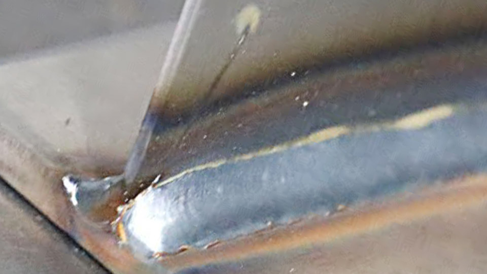
Image by @TimWelds
Why Heat Distribution Creates the Core Problem
Unequal thickness changes how heat flows through the joint and forces every setting decision.
Differential Melting and Heat Sink Behavior
The thin section reaches melting temperature quickly and has little mass to absorb excess energy. The thick section conducts heat away rapidly, so the same arc that burns the sheet leaves the plate barely fused. Heat input must therefore be biased toward the thick member while total energy stays low enough to protect the thin edge.
Typical Defect Patterns That Signal Incorrect Heat Balance
Burn-through or excessive melt-back on the thin side indicates the arc spent too much time or energy there. Lack of fusion or a cold lap on the thick side shows insufficient energy transfer.
Undercut along the thin toe often appears when travel speed is too slow or the arc is centered on the thin edge. Recognizing these patterns allows immediate correction of angle, amperage, or sequence.
Selecting the Welding Process for Unequal Thickness
Process choice determines how precisely heat can be directed and how much skill is required.
TIG for Maximum Control on Critical Joints
TIG allows independent control of amperage, pulse, and filler addition. The focused arc and ability to dab filler only when needed make it the most reliable process when the thickness ratio exceeds 3:1 or when appearance and strength both matter.
Typical amperage is set primarily for the thin member, then the torch is biased toward the thick side so the puddle expands into the plate.
MIG and Pulsed MIG for Production Speed
Short-circuit or pulsed MIG transfers heat efficiently while limiting overall input. Pulsed modes reduce average current and help prevent burn-through on sheet while still penetrating the plate.
Standard short-circuit transfer works for ratios up to about 4:1 when voltage and wire speed are kept at the lower end of the thin-material range and travel is directed onto the thick edge.
Stick Welding Limitations and Practical Use
Stick is least forgiving because the arc is less focused and slag must be managed. Small-diameter electrodes (3/32″ or 1/8″ low-hydrogen or 6013) run at the bottom of their amperage range and are angled strongly toward the thick plate.
Stick is viable for structural field work where portability matters, but it requires more skill to avoid burn-through than TIG or pulsed MIG.
Joint Preparation That Equalizes the Thermal Challenge
Preparation reduces the effective thickness difference and improves fusion probability.
Edge Preparation on the Thick Member
A single bevel of 30–45° on the thick plate creates a shelf that accepts the thin edge and gives the arc a larger surface to heat. Leaving a small root face (1/16″–3/32″) prevents the thin sheet from dropping into the joint.
On very thick plate a double bevel or J-groove further reduces the volume of weld metal needed while still directing heat into the mass.
Fit-Up, Gap, and Alignment Decisions
Maintain a consistent 1/32″–1/16″ gap for most processes so the arc can reach the thick root without forcing excessive filler into the thin edge. Clamp the thin sheet firmly against a backing bar or heat sink when possible.
Misalignment that leaves the thin edge proud of the thick face almost guarantees burn-through; keep the thin edge flush or slightly recessed.
Directing Heat and Controlling Input During the Weld
Technique determines whether the settings succeed or fail.
Torch or Electrode Angle Toward the Thick Side
Point the arc 60–80% onto the thick member so the puddle forms there first, then wets the thin edge. A 10–20° travel angle directed into the thick plate keeps the force of the arc pushing molten metal against the heat sink. Centering the arc on the thin edge is the fastest route to a hole.
Heat Sinks, Backing, and Clamping Strategies
Copper or aluminum backing bars under the thin sheet extract excess heat and support the puddle. Temporary clamps or strongbacks reduce distortion and keep the thin edge from lifting as it expands. On long seams, alternating short welds from the center outward limits cumulative heat buildup.
Travel Speed, Weaving, and Sequence Choices
Higher travel speed on the thin side reduces dwell time. Stringer beads are preferred over wide weaves because they deposit less heat per unit length. Skip welding or back-stepping sequences keep the overall heat input low and allow each segment to cool before the next is placed.
Practical Settings by Process and Thickness Ratio
Settings are chosen primarily from the thin member’s requirements, then adjusted for fusion into the thick side.
TIG Settings for Common Combinations
For 16-gauge (0.060″) sheet to ¼” plate on mild steel, start at 70–90 A DCEN with a 1/16″ or 3/32″ tungsten. Pulse at 1–2 Hz if available, with peak current high enough to wet the thick edge and background current low enough to freeze the thin edge. Add ER70S-2 or ER70S-6 filler only after the puddle has formed on the thick side.
MIG Settings for Sheet-to-Plate Work
On 18-gauge to ⅜” plate using 0.030″ or 0.035″ ER70S-6 wire and C25 gas, run 16–18 V and 150–220 inches per minute wire speed in short-circuit mode. Direct the gun so the wire aims at the thick edge.
Pulsed MIG allows slightly higher peak currents while keeping average heat lower; follow the machine’s thin-material synergic program and then bias the torch.
Stick Settings When That Is the Only Option
Use 3/32″ 7018 or 6013 at 70–95 A for 1/8″ sheet to ½” plate. Maintain a very short arc and a steep angle into the thick member. Vertical-up or overhead positions become especially difficult; reduce current another 5–10 A and use short stringers.
| Process | Thin Member | Thick Member | Starting Parameters | Key Adjustment |
|---|---|---|---|---|
| TIG | 16 ga | 1/4″ | 70–90 A DCEN | Bias arc 70% to thick |
| MIG | 18 ga | 3/8″ | 16–18 V, 180 ipm | Aim wire at thick edge |
| Stick | 1/8″ | 1/2″ | 75–90 A, 3/32″ rod | Short arc, steep angle |
Managing Distortion and Residual Stress
Unequal heating creates angular distortion and residual tensile stress concentrated on the thin side.
Sequencing and Residual Heat Management
Weld short segments and allow cooling between passes. On large assemblies, balance welds on opposite sides of the neutral axis when geometry permits. Monitor interpass temperature on the thin member; keep it below 300 °F for most mild steels to limit distortion and softening.
Post-Weld Correction Options
Mechanical straightening or controlled peening of the thin side can relieve residual stress after the joint cools. Avoid heavy grinding that further thins the already vulnerable edge.
For critical structures, a low-temperature stress-relief cycle may be specified, but it must stay below the tempering range of any heat-treated thick member.
Filler Metal and Consumable Decisions
Filler strength and deposition rate must match the joint requirements without overloading the thin side.
Matching or Undermatching Strength
For mild steel, ER70S-6 or E7018 provides adequate strength. When the thick member is higher-strength steel, an undermatching filler can reduce residual stress and cracking risk on the thin side. Stainless or aluminum joints follow the same heat-direction rules but require process-specific filler and shielding.
Wire or Rod Diameter Selection
Smaller diameters (0.030″ MIG wire, 1/16″ TIG filler, 3/32″ stick electrodes) deposit less heat per unit time and give finer control. Larger consumables increase deposition but raise the risk of burn-through unless travel speed is increased proportionally.
Wrapping Up
The successful thin-to-thick weld is defined by complete fusion into the thick member without melting a hole in the thin edge. Direct the majority of arc energy onto the thicker section, keep total heat input low through process choice and travel speed, and prepare the joint so the thin edge sits in a protected position.
Advanced operators further reduce risk by combining pulsed current with copper heat sinks and back-step sequences, producing joints that meet structural requirements while preserving the integrity of the thinner component.
FAQs
What is the best welding process for thin metal to thick metal?
TIG offers the highest control for critical work. Pulsed MIG is fastest for production. Stick works only with small electrodes and careful technique when portability is required.
How do you stop burn-through when welding thin sheet to thick plate?
Bias the arc strongly onto the thick member, increase travel speed, use heat sinks or backing, and set parameters for the thin thickness rather than the thick one.
Can you MIG weld 16-gauge to 1/4-inch steel successfully?
Yes. Use short-circuit or pulsed transfer at 16–18 V with 0.030–0.035″ wire, aim the arc at the thick edge, and maintain steady travel.
Should the amperage be set for the thin or the thick metal?
Set primary parameters for the thin metal to avoid burn-through, then adjust angle and technique so the puddle still fuses into the thick metal.


