Choosing the wrong amperage, gas flow, or pulse settings can make TIG welding unnecessarily difficult, even when using the correct filler metal and technique.
A reliable TIG Welding Settings Chart helps match machine parameters to material type, thickness, and welding conditions, reducing the risk of burn-through, poor penetration, excessive heat input, and unstable arc performance.
Stainless steel, mild steel, and aluminum each respond differently to heat, so using identical settings across materials can lead to inconsistent weld quality and unnecessary rework. Proper parameter selection also improves puddle control, bead appearance, and overall welding efficiency.
Understanding how to adjust amperage, AC/DC mode, tungsten size, electrode preparation, and shielding gas flow will help you establish more accurate starting settings and make practical adjustments for cleaner, stronger, and more consistent TIG welds.
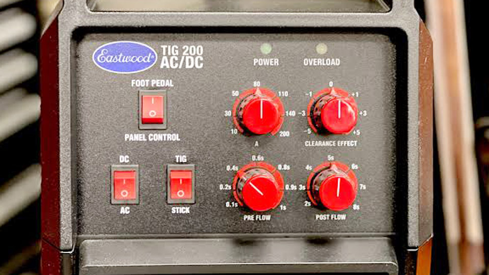
Image by eastwood
Core Amperage Ranges by Metal Type and Thickness
Amperage is the primary heat-input control. Most charts begin with the classic 1 amp per 0.001 inch rule for mild steel on DCEN, then adjust for thermal conductivity and joint type.
Mild Steel DCEN Settings
Mild steel dissipates heat quickly, so the full rule applies cleanly on thicknesses up to roughly ¼ inch. Use 2 % lanthanated or thoriated tungsten sharpened to a 20–30° point and 100 % argon.
| Thickness | Amperage Range | Tungsten | Filler Rod | Cup | Gas Flow |
|---|---|---|---|---|---|
| 0.035–0.060″ | 30–60 A | 1/16″ | 0.040–1/16″ | #4–#6 | 10–15 CFH |
| 1/16–3/32″ | 50–90 A | 1/16″ | 1/16″ | #5–#7 | 15–20 CFH |
| 1/8″ | 80–130 A | 1/16–3/32″ | 3/32″ | #6–#8 | 15–20 CFH |
| 3/16″ | 120–180 A | 3/32″ | 1/8″ | #7–#8 | 20–25 CFH |
| 1/4″ | 150–220 A | 3/32–1/8″ | 1/8″ | #8–#10 | 20–25 CFH |
| 3/8″ | 200–280 A | 1/8″ | 3/16″ | #8–#10 | 20–30 CFH |
Start near the middle of the band for a flat butt joint and raise 10–15 A for fillets or vertical-up work. Foot-pedal control lets the operator ramp current after the arc is established, preventing cold starts.
Stainless Steel Adjustments
Stainless retains heat longer than mild steel, so drop amperage 10–15 %. Back-purging the root is non-negotiable on pipe or any joint that must remain free of sugaring. ER308L or ER316L filler matches common 304/316 base metals.
| Thickness | Amperage Range | Tungsten | Filler Rod | Notes |
|---|---|---|---|---|
| 0.040–1/16″ | 30–70 A | 1/16″ | 0.045–1/16″ | Short arc, fast travel |
| 1/8″ | 70–115 A | 1/16–3/32″ | 3/32″ | Pulse optional for heat control |
| 3/16″ | 100–160 A | 3/32″ | 1/8″ | Gas lens recommended |
| 1/4″ | 130–190 A | 3/32–1/8″ | 1/8″ | Multi-pass, interpass control |
Travel speed must stay high enough to limit heat-affected-zone growth; otherwise chromium carbides form and corrosion resistance drops.
Aluminum AC Settings
Aluminum’s high thermal conductivity and tenacious oxide demand AC polarity and higher current. Balance is typically set 65–75 % electrode-negative for penetration while still providing cleaning action. Pure argon remains standard; helium mixes raise heat on thick sections.
| Thickness | Amperage Range | Tungsten | Filler Rod | Cup | Gas Flow |
|---|---|---|---|---|---|
| 1/16″ | 60–100 A | 1/16″ | 1/16″ | #5–#6 | 15–20 CFH |
| 3/32″ | 90–130 A | 1/16–3/32″ | 3/32″ | #6–#7 | 15–20 CFH |
| 1/8″ | 120–160 A | 3/32″ | 3/32–1/8″ | #7–#8 | 15–20 CFH |
| 3/16″ | 160–220 A | 3/32–1/8″ | 1/8″ | #8 | 20–25 CFH |
| 1/4″ | 210–280 A | 1/8″ | 5/32–3/16″ | #8–#10 | 20–30 CFH |
Preheat thicker plate above ¼ inch to 200–300 °F to stabilize the puddle and reduce the risk of incomplete fusion at the root.
Tungsten Diameter Selection Linked to Current Capacity
Electrode size must contain the selected amperage without melting or excessive balling. Alloyed tungsten (2 % lanthanated, ceriated, or thoriated) carries higher current than pure tungsten on DCEN.
Rated Ranges for Common Alloyed Electrodes
- 1/16″ (1.6 mm): 50–160 A DCEN / 50–150 A AC
- 3/32″ (2.4 mm): 135–235 A DCEN / 130–250 A AC
- 1/8″ (3.2 mm): 250–400 A DCEN / 225–360 A AC
Choose the smallest diameter that safely covers the upper end of the intended amperage band. On AC aluminum the tip forms a controlled ball; on DCEN the tip remains pointed for a tight arc column.
Stick-Out and Cup Relationship
Gas-lens collets allow stick-out up to the inside diameter of the cup without turbulence. Standard collets limit stick-out to roughly one electrode diameter. Longer stick-out improves visibility in tight corners but demands higher gas flow or a larger cup to maintain shielding.
Shielding Gas Flow and Cup Sizing Decisions
Argon flow is governed by cup orifice size and joint geometry rather than amperage alone.
Practical Flow Guidelines
- #5–#6 cup: 10–15 CFH on thin sheet
- #7–#8 cup: 15–20 CFH for most shop work
- #10 cup or gas lens: 20–30 CFH on open corners or outdoor drafts
Post-flow should equal approximately 5 seconds per millimeter of tungsten diameter so the electrode cools under shielding and avoids contamination. Outside corner joints on stainless often need 1.5× normal flow to prevent oxidation on the backside of the bead.
Joint Type and Position Effects on Starting Amperage
Charts assume flat-position butt joints with tight fit-up. Real joints shift the numbers.
Fillet Versus Butt Versus Open-Root
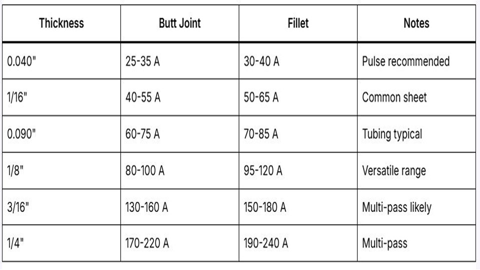
Fillet joints pull heat in three directions and typically require 10–20 A more than a butt joint of the same thickness. Open-root welds run 10–15 A lower so the keyhole stays controllable. Vertical-up work drops another 10–15 % from the flat setting; overhead follows a similar reduction to keep the puddle from sagging.
Pulse Parameters for Heat Control
When the machine offers pulse, set peak time 40–50 %, background current 20–30 % of peak, and frequency 1–2 Hz for thin stainless or aluminum sheet. Higher pulse rates (100+ PPS) narrow the arc and raise travel speed on production fillet work. Pulse does not replace correct average amperage; it only modulates the heat delivery cycle.
Matching Filler Diameter to Base Thickness and Amperage
Filler that is too large chills the puddle; filler that is too small requires excessive current to melt and can produce underfill. Match filler diameter to roughly the same size as the tungsten or one step smaller than material thickness on thin sheet. Common pairings:
- 1/16″ material → 1/16″ or 0.045″ filler
- 1/8″ material → 3/32″ filler
- 3/16–1/4″ material → 1/8″ filler
Add filler only after the puddle is established and wet; dipping too early freezes the pool and leaves incomplete fusion at the toes.
Machine-Specific Factors That Alter Chart Values
Inverter machines with advanced square-wave or high-frequency AC often run 10–15 % lower amperage than older transformer units for the same puddle fluidity because of tighter arc control. Cable length and torch type introduce voltage drop; long leads may require a slight amperage increase to compensate. Always verify the actual output with a clamp meter if the machine display and bead behavior disagree.
Selecting the correct line on a TIG welding settings chart is only the first decision. Once the puddle forms, the operator still adjusts travel speed, arc length (ideally one electrode diameter or less), and torch angle to keep the bead geometry and heat-affected zone inside specification. Advanced operators further refine heat input by combining short-arc technique with deliberate stringer beads and controlled interpass temperature rather than relying solely on the starting amperage number.
What amperage for 1/8 inch mild steel TIG?
80–130 A DCEN with 1/16″ or 3/32″ lanthanated tungsten. Start near 100–110 A on a flat butt joint and raise 10–15 A for fillets.
How many amps for 1/8 inch aluminum TIG welding?
120–160 A on AC with 65–75 % electrode-negative balance. Use 3/32″ tungsten and 15–20 CFH argon.
What gas flow rate for TIG welding?
15–20 CFH for most #6–#8 cups on steel and stainless; raise to 20–25 CFH on aluminum or open joints. Post-flow 8–12 seconds for 3/32″ tungsten.
Do I use the same amps for stainless as mild steel?
No. Drop 10–15 % from the mild-steel value at the same thickness to limit heat retention and prevent carbide precipitation.