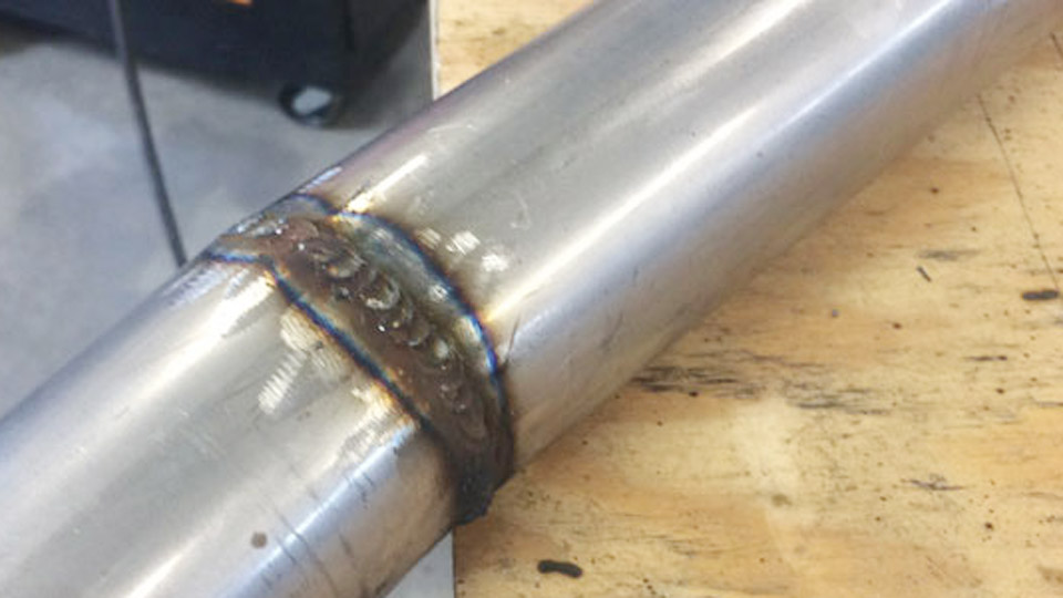
Many welders struggle with inconsistent bead profiles, excessive spatter, burn-through on thin materials, or lack of control in out-of-position work when using standard MIG. Pulse MIG welding addresses these issues by delivering controlled droplet transfer, lower average heat input, and cleaner results.
A reliable Pulse MIG Welding Settings Chart becomes essential for dialing in voltage trim, wire feed speed (WFS), peak/background currents, and other parameters across materials and thicknesses.
This guide provides practical, high-density settings data and decision-making insights tailored for DIYers, students, hobbyists, and pros seeking real-world performance.
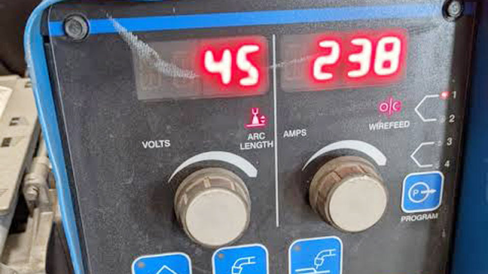
Image by r/Welding
Understanding Pulse MIG Transfer and Why Settings Matter
Pulse MIG modifies spray transfer by rapidly switching between high peak current (pinching off and propelling a droplet) and low background current (maintaining the arc without transfer). This cycle, often hundreds of times per second, reduces overall heat input while enabling spray-like deposition.
Key advantages over constant voltage MIG include minimized distortion, near-zero spatter, better puddle control in all positions, and the ability to use larger-diameter wires on thinner materials.
Synergic controls on modern machines simplify setup by linking WFS to optimal voltage/trim, but manual overrides and fine-tuning remain critical for joint type, position, and fit-up variations.
Settings charts serve as starting points. Actual values depend on machine model, shielding gas, wire type/diameter, base material, joint preparation, and technique. Always verify with test welds and monitor average voltage and arc sound.
Core Pulse MIG Parameters Explained
Wire Feed Speed (WFS) and Amperage Relationship
WFS primarily controls deposition rate and amperage. In pulse mode, higher WFS increases average current within the pulsed waveform. Use manufacturer synergic programs as a base, then adjust.
Typical multipliers for initial WFS estimation (adapt for pulse):
- .030″ wire: ~2 ipm per amp
- .035″ wire: ~1.6 ipm per amp
- .045″ wire: ~1 ipm per amp
For pulse, target WFS that keeps the process in the pulsed spray regime without dropping into globular.
Voltage Trim / Arc Length Control
Most pulse machines replace fixed voltage with “trim” (e.g., 0.50–1.50 scale, where 1.00 is optimal). Trim adjusts arc length: lower values shorten the arc for better control and penetration; higher values lengthen it for wider beads or hotter puddle.
- Trim < 1.00: Tighter arc, less spatter risk on thin material, better vertical control.
- Trim > 1.00: Longer arc, improved wetting on thicker sections or fillets.
Monitor displayed average voltage during welding.
Pulse-Specific Controls
- Peak Current: Determines droplet detachment force. Higher for thicker materials or better penetration.
- Background Current: Typically 20–50% of peak; maintains arc stability with minimal heat.
- Pulse Frequency: 50–300+ Hz. Higher frequency for smoother beads and thinner materials.
- Pulse Width / Duty Cycle: Percentage of time at peak current. Affects heat balance.
- Double Pulse (Pulse-on-Pulse): Adds a secondary low-frequency pulse (e.g., 1–10 Hz) for ripple effect, superior heat control, and TIG-like appearance, especially on aluminum and stainless.
Pulse MIG Settings for Mild Steel
Mild steel benefits from pulse for cleaner welds on thin-to-medium thicknesses and out-of-position work. Use 80–90% Ar / 10–20% CO2 gas for optimal spray transition.
Recommended Starting Settings Chart ( .035″ ER70S-6 wire, 90/10 Ar/CO2, flat position fillets):
| Thickness | WFS (ipm) | Trim (1.0 base) | Approx. Avg Amps | Notes |
|---|---|---|---|---|
| 16–14 ga (~0.06–0.08″) | 180–280 | 0.85–1.05 | 80–140 | Low heat; push technique |
| 1/8″ (0.125″) | 250–350 | 0.95–1.10 | 140–180 | Good penetration |
| 3/16″ | 320–420 | 1.00–1.15 | 170–220 | Balance speed |
| 1/4″ | 380–480 | 1.05–1.20 | 200–250 | Increase trim for wider bead |
| 3/8″–1/2″ | 450–550+ | 1.10–1.30 | 220–300+ | Higher deposition; watch distortion |
Adjust trim down for vertical-up (tighter puddle) and test for undercut. Larger .045″ wire allows higher deposition on thicker plates.
Position and Joint Adjustments for Steel
- Vertical/Overhead: Reduce WFS 10–20%, lower trim for stiffer puddle. Use shorter stickout (5/8″).
- Root Passes vs. Fills: Lower trim and frequency for roots to improve fusion; higher for caps.
- Travel Speed: Pulse enables 20–50% faster speeds than short-circuit, reducing heat input.
Pulse MIG Settings for Stainless Steel
Stainless demands low heat to prevent sensitization and distortion. Use 98% Ar / 2% CO2 or tri-mix gases. Limit CO2 to ≤5%.
Starting Chart (.035″ ER308L/316L, flat):
| Thickness | WFS (ipm) | Trim | Approx. Avg Amps | Pulse Notes |
|---|---|---|---|---|
| 16–18 ga | 150–250 | 0.80–1.00 | 70–130 | High frequency for thin sheets |
| 1/8″ | 220–320 | 0.90–1.10 | 120–170 | Excellent wetting |
| 1/4″ | 300–400 | 1.00–1.20 | 160–220 | Double pulse for cosmetics |
| 3/8″+ | 380–500 | 1.05–1.25 | 200–280 | Monitor interpass temps |
Stainless puddle is sluggish—push at 10–15° travel angle. Double pulse creates stacked dimes appearance with minimal cleanup.
Gas and Wire Considerations
Higher argon content improves arc stability. For heavy sections, consider helium blends for hotter arc if needed, but test for porosity.
Pulse MIG Settings for Aluminum
Aluminum’s high thermal conductivity and oxide layer make pulse ideal. Use 100% Argon or Ar/He mixes. Pure argon for most; helium for thicker sections.
Starting Chart (.035″ or .047″ ER4043/5356, flat):
| Thickness | WFS (ipm) | Trim | Approx. Avg Amps | Special Adjustments |
|---|---|---|---|---|
| 1/16–1/8″ | 200–350 | 0.90–1.10 | 90–160 | Higher start current for oxide breakthrough |
| 3/16–1/4″ | 300–450 | 1.00–1.20 | 150–230 | Double pulse preferred |
| 3/8″+ | 400–600+ | 1.05–1.30 | 200–300+ | He blends; longer stickout possible |
- Push Technique Mandatory: 10–15° angle.
- Hot Start: Increase start current 10–30% for clean fusion.
- Craters: Use end slope and lower end current to fill.
Double pulse excels here for ripple aesthetics and reduced distortion.
Aluminum-Specific Challenges
Clean material thoroughly (stainless brush, acetone). Watch for porosity from moisture or improper gas coverage. Maintain 5/8–3/4″ stickout.
Advanced Parameter Optimization and Machine Controls
Synergic vs. Manual Mode
Synergic programs select base parameters by material/wire/thickness. Use them for consistency, then fine-tune trim, inductance (if available), and pulse variables. Manual mode offers full control for experienced users but requires more testing.
Double Pulse Tuning
- Frequency (Hz): 1–5 Hz for visible ripples.
- Balance (%): Higher main pulse time increases heat/penetration.
- Ideal for cosmetic applications or thin materials.
Technique and Setup Best Practices
- Stickout: 5/8–3/4″ (longer than short-circuit).
- Gun Angle: 45° work angle, 10–15° push travel.
- Grounding: Clean, secure connections to prevent voltage drop.
- Wire Feed Consistency: Critical for pulse stability—ensure proper drive rolls and tension.
Test on scrap matching your job. Evaluate bead: convex profile with good tie-in, no undercut, minimal spatter.
Troubleshooting Common Pulse MIG Issues
Inconsistent Arc / Spatter:
- Increase trim slightly or check gas flow (20–30 CFH).
- Verify wire feed system; adjust contact tip to work distance.
Lack of Penetration:
- Increase WFS/peak current or reduce travel speed.
- Ensure proper joint prep and fit-up.
Burn-Through / Distortion:
- Lower WFS, increase travel speed, or switch to double pulse.
- Use backing bars or pulse settings optimized for thin material.
Porosity:
- Clean base metal, check gas purity/coverage, reduce arc length.
Poor Start/End:
- Adjust start/end current and slope times.
Machine-specific manuals provide the most accurate baselines—cross-reference with these charts.
Selecting Equipment and Wire for Pulse Performance
Choose machines with robust synergic pulse programs, push-pull capability for aluminum, and proven reliability. Larger wire diameters (e.g., .045″ vs .035″) reduce cost per pound and allow higher deposition in pulse mode.
Match wire to application: ER70S-6 for steel (better on dirty material), silicon-bronze for MIG brazing thin auto body, 4043 vs 5356 for aluminum strength/aesthetics.
Real-World Applications and Decision Framework
For production manufacturing, pulse MIG boosts travel speeds and reduces post-weld labor. In fabrication shops, it handles mixed thicknesses and positions efficiently. Hobbyists gain TIG-like results without the learning curve or speed penalty.
Decision Factors:
- Thin or distortion-prone material → Prioritize pulse/double pulse.
- Heavy structural → Pulse for speed and cleanliness over short-circuit.
- Appearance-critical (food-grade, architectural) → Double pulse stainless/aluminum.
- Budget/Training → Synergic machines lower the barrier.
Always qualify settings to your WPS and perform destructive or visual tests.
Performance Takeaway
Mastering a Pulse MIG Welding Settings Chart empowers consistent, high-quality welds by balancing deposition, heat, and control.
The pro-level insight is recognizing that optimal parameters are dynamic—integrate real-time feedback from arc sound, puddle behavior, and bead geometry with data-driven starting points to outperform conventional MIG in efficiency and quality.
FAQ
What is the best shielding gas for pulse MIG on mild steel?
90% Ar / 10% CO2 provides excellent arc stability and low spatter in pulsed spray transfer. Higher argon for even cleaner results if penetration allows.
How do I convert standard MIG settings to pulse?
Start with synergic program for your wire/thickness, then use trim around 1.0 and adjust WFS for desired amperage. Reduce overall heat input compared to CV spray by leveraging background current.
Does pulse MIG work well for vertical welding?
Yes—superior puddle control allows all-position welding. Lower WFS/trim and higher pulse frequency help manage the molten pool effectively.
Can I use pulse MIG for MIG brazing?
Absolutely. Bronze wires on thin or coated steels benefit from precise low-heat control, preserving base material properties with minimal distortion.