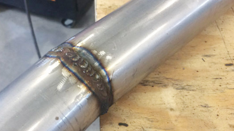
Uneven beads, undercut, excessive spatter, and lack of fusion often trace directly to an unstable or incorrect gun hold rather than machine settings alone.
Mastering how to hold a MIG welding gun determines arc stability, shielding-gas coverage, penetration depth, and bead profile more than any single parameter adjustment.
A loose or death-grip hold introduces shake that widens the arc and breaks gas coverage; the wrong travel or work angle redirects heat and metal transfer away from the joint root.
For structural, fabrication, and repair work, the difference between a sound weld and a reject frequently begins with hand placement, bracing, and the 5–15° angle window relative to the joint.
Correct technique keeps contact-tip-to-work distance consistent and lets the operator focus on travel speed instead of fighting the gun.
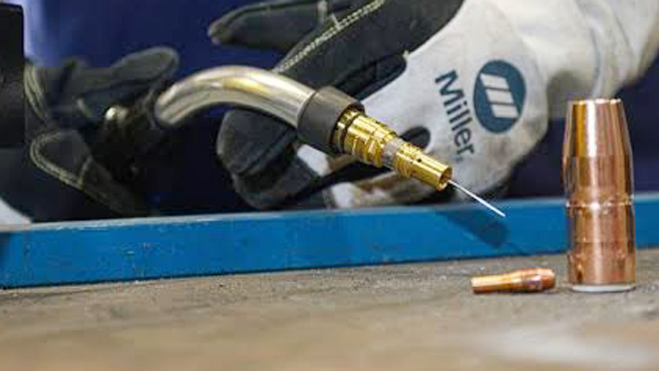
Image by thefabricator
Establishing a Stable Grip That Controls the Arc Without Fatigue
A secure yet relaxed grip is the foundation of every successful MIG pass. Tension in the hand or forearm transmits directly into gun movement and produces an irregular arc column.
Dominant-Hand Placement and Trigger Finger Position
Wrap the dominant hand around the handle in a handshake-style grip—firm enough to prevent slip, loose enough to avoid white-knuckle fatigue. The index finger rests naturally on the trigger so a light pull activates wire feed without shifting the entire gun.
Middle and ring fingers support under the handle or barrel; the thumb rests lightly on top or along the side for directional micro-adjustments.
Pinching too far forward or too far back changes leverage and makes stickout harder to maintain. The goal is a neutral wrist that does not cock upward or downward under load.
Support-Hand Role for Precision and Reduced Shake
The non-dominant hand stabilizes rather than drives the gun. Common methods include cradling the underside of the handle or nozzle area, supporting the dominant wrist or forearm, or resting the support hand on a stable surface while lightly contacting the gun.
This two-handed approach markedly reduces tremor during longer beads. Avoid stacking both hands in a way that forces the trigger to be depressed with the helmet raised or creates a pivot that rolls the gun off-axis. Keep the support hand far enough from the arc to limit heat transfer while still providing a rigid brace.
Bracing Techniques That Lock Consistency
Whenever joint access allows, rest the heel of the dominant hand, the forearm, or the elbow against the workpiece, a table edge, or a fixed fixture. This converts free-floating arm motion into a controlled slide and keeps contact-tip-to-work distance nearly constant.
Pulling the elbow into the rib cage shortens the lever arm and improves visibility under the nozzle. Cable weight should be managed over the shoulder or with a boom so it does not constantly tug the gun sideways and force continuous correction.
Setting Travel Angle and Work Angle for Joint Geometry
Two independent angles govern heat direction, metal transfer, and gas coverage. Exceeding the practical limits of either angle produces measurable defects.
Push Versus Drag Decisions and Resulting Bead Characteristics
Travel angle is measured from perpendicular in the plane of travel and is normally held between 5° and 15°.
- Push (forehand) technique tilts the gun 5–15° in the direction of travel so the wire points ahead of the puddle. It produces a flatter, wider bead with shallower penetration, improved visibility of the joint, and often better gas coverage ahead of the arc. It is preferred on thinner material and aluminum.
- Drag or pull (backhand) technique tilts the gun 5–15° opposite the direction of travel so the wire points back into the puddle. It concentrates heat for deeper penetration and a narrower, more convex bead. It is favored on thicker plate when full fusion is required.
Angles beyond approximately 20–25° destabilize the arc, increase spatter, reduce penetration, and degrade shielding. Choose the technique according to required penetration and material thickness rather than habit.
Work Angles Matched to Butt, Fillet, and Lap Joints
Work angle is measured in the plane perpendicular to travel.
- Flat butt (groove) joints: 90° to the surface so the arc bisects the joint.
- Fillet or T-joints: 45° so heat and filler are shared equally between the two members.
- Lap joints: approximately 60°, or biased 10° toward the thicker member if thicknesses differ, to avoid burn-through on the thinner edge.
- Horizontal fillets: 30–60° to counteract gravity and prevent the bead from rolling over the lower toe.
Incorrect work angle produces undercut on one side and incomplete fusion on the other. Aim the contact tip at the root of the joint rather than the face of the plates.
Adjusting the Hold Across Welding Positions
Gravity changes puddle behavior, so grip pressure, bracing, and angles must adapt while the fundamental 5–15° travel window remains.
Flat and Horizontal Control
In the flat position the gun can be held with minimal bracing because the puddle stays in place. A 5–15° push is common for visibility and bead appearance; drag is used when deeper penetration is needed.
Horizontal work requires a work angle that favors the upper plate slightly and a steady brace to stop the molten metal from sagging. Maintain the same stickout and travel speed used in flat; any change in angle is purely to counteract gravity.
Vertical-Up and Vertical-Down Requirements
Vertical-up (uphill) on material ¼ in and thicker benefits from a slight upward tilt of the gun (often 5–10° from horizontal) combined with a 45° work angle on fillets. A controlled weave or upside-down-V motion can be used while keeping travel slower than flat.
Vertical-down (downhill) suits thinner gauges; the gun is pointed more steeply upward relative to the joint so the arc stays ahead of the fast-moving puddle.
In both cases, reduce voltage and wire-feed speed 10–15 % from flat-position settings to keep the puddle manageable. Choking up slightly on the gun improves fine control of the weave.
Overhead Stability Techniques
Overhead demands the most rigid body position. Keep the gun nearly perpendicular to the joint (0–10° travel angle) so arc force helps hold metal in place. Shorten stickout, increase travel speed, and keep beads small—stringers rather than wide weaves.
Brace the gun arm against the body or structure whenever possible and route the cable so it does not pull downward. Faster freeze and reduced parameters (again 10–15 % lower than flat) minimize dripping. Visibility is improved by positioning the head off to the side rather than looking straight down the nozzle.
Maintaining Contact-Tip-to-Work Distance and Gun Orientation
Stickout (contact-tip-to-work distance) is typically held between ⅜ in and ½ in for solid-wire MIG on steel. Shorter stickout increases current and penetration; longer stickout lowers current, widens the bead, and risks porosity from poor gas coverage.
The grip and bracing technique must keep this distance constant while the gun travels. Any change in wrist angle or forearm height alters stickout and therefore amperage delivered at the arc.
Cable drag is a frequent hidden variable. Excess cable weight or a sharp bend near the gun handle forces continuous corrective torque. Route the cable over the shoulder or use a swivel and boom so the only force the operator feels is the light weight of the gun itself.
Consistent orientation of the nozzle relative to the joint also preserves gas flow; tilting the gun excessively starves one side of the puddle of shielding.
Matching Grip Pressure and Angle to Material Thickness and Transfer Mode
On thin sheet (16 ga–⅛ in) a lighter grip and push technique with 5–10° travel angle limit heat input and reduce burn-through risk. Stickout stays on the shorter side of the range.
Medium plate (3/16–⅜ in) accepts either push or drag at 10–15°; the choice depends on whether a flat cosmetic bead or deeper fusion is required.
Heavy plate often uses drag for maximum penetration and may require a slightly firmer brace because higher amperage increases gun reaction force.
Wrapping Up
Short-circuit transfer favors a stable, short stickout and precise angle control because the puddle is small and freezes quickly. Spray or pulsed spray allows a slightly longer stickout and benefits from a consistent push for gas coverage, but the same fundamental grip and angle rules apply.
In every case the operator’s decision tree starts with joint type and position, then selects travel technique, then locks the grip and brace that will hold those angles for the length of the bead.
A correct hold produces a steady hissing or sizzling arc sound, a consistent stickout, and a bead whose toes fuse cleanly without undercut or cold lap. When the gun is positioned so the operator can see the leading edge of the puddle and the joint line simultaneously, micro-corrections become possible in real time.
Advanced operators further refine performance by matching neck angle and handle geometry of the gun itself to the predominant joint access on a given job, reducing the need for extreme wrist deviation and extending productive time before fatigue sets in.
FAQs
What is the correct angle to hold a MIG welding gun?
Maintain a travel angle of 5–15° (push or drag) and a work angle matched to the joint—90° for flat butts, 45° for fillets. Exceeding roughly 20° travel angle increases spatter and reduces penetration.
Should I push or pull the MIG gun?
Push (forehand) for thinner material, flatter beads, and better visibility. Drag (backhand) for thicker plate when deeper penetration is required. Both stay inside the 5–15° window.
How far should the MIG gun be from the metal?
Keep contact-tip-to-work distance (stickout) between ⅜ in and ½ in for most solid-wire steel applications. Shorter stickout raises current; longer stickout lowers it and risks poor gas coverage.
How do I hold a MIG gun for overhead welding?
Hold the gun nearly perpendicular with a 0–10° travel angle, use a rigid brace, shorten stickout, travel faster, and reduce voltage and wire speed 10–15 % from flat settings to keep the puddle from falling.