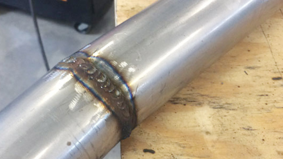
Many fabricators discover the hard way that a MIG weld on 4130 tubing that looks solid on the bench can crack under cyclic load or fail a sanctioning-body inspection. The question can you MIG weld chromoly is not a simple yes-or-no—the answer depends on wall thickness, joint criticality, filler choice, and heat-input control.
Chromoly’s moderate carbon and alloy content give it excellent strength-to-weight performance, yet the same chemistry raises hardenability in the heat-affected zone. Excess heat or the wrong filler turns a high-strength tube into a brittle joint.
Understanding the practical boundaries lets you decide when MIG is acceptable, when it is restricted, and how to produce reliable results when you choose it.
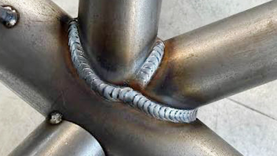
Image by fb
When MIG Welding 4130 Chromoly Is Acceptable Versus Restricted
Sanctioning bodies and engineering standards draw clear lines based on risk.
Structural and Safety-Critical Applications
NHRA and many SFI specifications require TIG-only welding on 4130 chromoly roll cages and primary chassis members. The larger heat-affected zone and higher overall heat input of conventional MIG transfer increase the chance of reduced toughness.
Aircraft and high-performance suspension components follow the same preference for TIG because precise heat control preserves ductility.
Non-Critical or Production Fabrication
MIG becomes practical on thicker sections (generally above 0.120 in wall), secondary brackets, bumper mounts, non-primary frame reinforcements, and production structural assemblies where speed matters more than ultimate fatigue performance.
Short-circuit or pulsed MIG with correct filler can deliver acceptable strength when heat input is deliberately limited and cooling is controlled.
Thickness Thresholds That Change the Decision
Below approximately 0.080–0.090 in wall thickness, burn-through risk and HAZ hardening rise sharply with MIG. Above 0.120 in, preheat becomes the dominant variable and MIG heat input is easier to manage. Between these limits, pulsed MIG or careful short-circuit technique can succeed if joint fit-up is tight and travel speed stays high.
Filler Metal Selection Decisions for 4130 MIG Welds
Filler chemistry determines whether the finished joint matches or under-matches the base metal and whether it remains ductile in the as-welded condition.
ER80S-D2 for Strength Matching
ER80S-D2 contains intentional molybdenum and elevated manganese. Deposited tensile strength typically falls in the mid-80 ksi range, closer to normalized 4130.
Use it when the weld must carry significant load and post-weld heat treatment is not planned. It is the most common recommendation from filler manufacturers for 4130-to-4130 joints that remain as-welded.
ER70S-2 or ER70S-6 for Ductility Priority
These mild-steel wires produce lower-strength but more ductile deposits. Dilution with the 4130 base metal still yields a joint in the 70–80 ksi range while improving elongation.
Fabricators often choose ER70S-2 on thin-wall tubing or on joints that must absorb impact energy without cracking. ER70S-6 works on clean material but offers less deoxidation margin than ER70S-2.
Matching 4130 Filler and Stainless Options
Matching 4130 filler produces high hardness and low ductility unless the entire assembly receives proper post-weld heat treatment. Avoid it on thin tubing and sporting applications.
Austenitic stainless fillers such as 310 or 312 are sometimes used for dissimilar joints; other stainless grades can promote cracking and should be avoided.
Preheat, Interpass Temperature, and Cooling Control by Thickness
Heat management prevents the formation of untempered martensite in the HAZ.
Thin-Wall Tubing Under 0.120 in
Preheat is generally unnecessary provided the material is at or above room temperature (approximately 70 °F). Focus on minimizing total heat input through short arc length, high travel speed, and pulsed or short-circuit transfer. Allow the weld to cool slowly in still air; forced cooling or quenching increases cracking risk.
Sections Above 0.120 in Wall
Preheat to 300–400 °F before welding. Maintain interpass temperature in a similar range. After welding, slow cooling is mandatory—wrap the joint or bury it in insulating material if ambient conditions cause rapid heat loss. For critical thick sections, a stress-relief cycle near 1100 °F may be specified by the procedure.
Interpass and Multi-Pass Considerations
On multi-pass joints, clean thoroughly between passes and keep interpass temperature controlled. Excess heat from successive passes can coarsen the HAZ microstructure even when the first pass was correctly executed.
Machine Settings and Transfer Modes That Limit Heat Input
Transfer mode and parameter selection determine whether MIG can approach TIG-level heat control.
Short-Circuit and Pulsed Transfer Preference
Short-circuit transfer keeps the arc energy low and is the practical choice for wall thicknesses under 0.100 in. Pulsed spray transfer further reduces average heat input while improving wetting and reducing spatter. Avoid globular transfer on thin chromoly; the higher energy and larger droplet size widen the HAZ.
Typical Starting Parameters for Common Wall Thicknesses
For 0.058–0.083 in wall with 0.030 in ER80S-D2 or ER70S-2 wire and 75/25 argon-CO₂:
- Voltage: 18–20 V
- Wire feed speed: 250–350 ipm
- Approximate amperage: 90–130 A
- Gas flow: 20–25 CFH
For 0.120 in and thicker with 0.035 in wire:
- Voltage: 19–22 V
- Wire feed speed: 240–300 ipm
- Amperage: 140–175 A range, adjusted to maintain short-circuit or pulsed transfer
Increase inductance (or select a stainless-steel program if available) to soften the arc and improve toe wetting. Always verify parameters on scrap of identical thickness and diameter before production welding.
Shielding Gas Choices
A 75 % argon / 25 % CO₂ blend is the most common and economical choice for MIG on 4130. Higher argon mixes (90/10 or 98/2) reduce spatter and can narrow the arc, but require parameter adjustment. Straight CO₂ increases penetration and heat input and is rarely preferred for thin tubing.
Joint Preparation and Technique Differences from Mild Steel
Chromoly demands tighter discipline than mild steel.
Surface and Fit-Up Requirements
Remove all mill scale, oil, and oxide to bright metal. Joint gaps should stay under 0.010 in for thin tubing; larger gaps force higher heat input to achieve fusion. Vent closed tubing sections to prevent pressure buildup and internal contamination.
Arc Length, Angle, and Travel Speed
Maintain a short arc length. A longer arc raises voltage and total energy, widening the HAZ. Use a slight push or neutral angle and travel fast enough to keep the puddle small. On thin tubing, continuous stringer beads or minimal weaving reduce cumulative heat.
Chromoly-to-Mild-Steel Transitions
ER70S-2 is the usual choice for these dissimilar joints because its lower strength and higher ductility accommodate the property mismatch. Clean both materials thoroughly and control heat on the chromoly side more carefully than on the mild-steel side.
Application Limits for Roll Cages, Chassis, and Structural Fabrication
Code compliance and service conditions dictate process choice more than technical possibility.
Certified Motorsport and Aerospace Work
TIG remains mandatory for primary chromoly structures under most racing and aviation rules. MIG welds on these parts will not pass inspection regardless of mechanical test results.
Secondary and Non-Primary Components
MIG is routinely used for tabs, brackets, cross-members that are not primary load paths, and repair work on thicker sections. Document filler, gas, and parameters so the joint can be evaluated against the intended service load.
Production Versus One-Off Fabrication
In high-volume structural work where every joint is non-critical, MIG with ER80S-D2 and controlled parameters offers speed advantages. For one-off high-performance parts, the extra time required for TIG usually yields a more consistent and inspectable result.
Wrapping Up
The decision to MIG weld chromoly rests on three technical filters: wall thickness above the thin-tube risk zone, joint criticality that does not trigger TIG-only rules, and disciplined heat-input control through filler selection, transfer mode, and cooling practice. When those conditions are met, ER80S-D2 or ER70S-2 in short-circuit or pulsed MIG produces serviceable joints.
When any filter fails, switch to TIG. Advanced fabricators further reduce risk by measuring actual heat input (voltage × current × time / travel distance) and correlating it with hardness traverses across the HAZ on representative coupons before committing to production parts.
FAQs
Can you MIG weld 4130 chromoly tubing for a roll cage?
Most sanctioning bodies, including NHRA, require TIG welding for 4130 chromoly primary structures. MIG is not accepted for certified cages regardless of technique.
What is the best MIG wire for chromoly?
ER80S-D2 for strength matching on structural joints that remain as-welded; ER70S-2 when higher ductility is preferred or when joining to mild steel.
Do you need to preheat chromoly before MIG welding?
Not for wall thicknesses under approximately 0.120 in if the material is at room temperature. Thicker sections require 300–400 °F preheat and controlled slow cooling.
Is MIG welding chromoly as strong as TIG?
Properly executed MIG can approach TIG joint strength on thicker material, but the larger heat-affected zone and reduced process control typically leave TIG with better toughness and fatigue performance on thin-wall tubing.