A gas oven that clicks or glows but never lights, or one that fills the kitchen with the smell of unburned fuel, almost always points to a problem in the safety valve circuit.
Understanding how a gas oven safety valve works removes the guesswork: the valve stays closed by default and opens only when a verified ignition source is hot enough to light the gas. That single requirement prevents explosive mixtures from forming inside the cavity.
For anyone who works with pressurized gas systems—whether fabricating, repairing appliances, or running shop equipment—the same principles of fail-safe current sensing, thermocouple voltage, and bimetal response appear repeatedly.
Correct diagnosis of current draw, millivolt output, and mechanical response decides whether the valve itself, the igniter, or the thermocouple must be replaced.
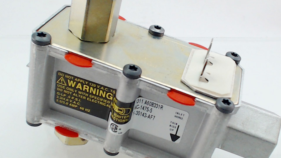
Image by seneca-river-trading
The Two Primary Safety Valve Designs in Gas Ovens
Modern and older gas ovens use different sensing methods, but both enforce the same rule: no gas flow without confirmed heat at the ignition point.
Thermocouple-Controlled Valves on Standing Pilot Systems
Older ranges keep a continuous pilot flame. A thermocouple probe sits in that flame. Two dissimilar metals joined at the tip generate 20–30 mV by the Seebeck effect once the tip reaches roughly 600–800 °C. That millivolt signal energizes a small electromagnet inside the safety valve body.
The magnet holds a spring-loaded plunger open against spring pressure, allowing gas to reach both the pilot and the main burner when the thermostat calls for heat.
If the pilot extinguishes, the tip cools within seconds, voltage collapses, the magnet releases, and the spring snaps the valve shut. Manual depression of the control knob is required to open the valve initially so the pilot can be lit and the thermocouple can generate its holding current.
Bimetal and Current-Sensing Valves with Hot Surface Igniters
Most ranges built after the mid-1980s eliminate the standing pilot. A silicon-carbide or silicon-nitride glow-bar igniter and the safety valve sit in series on a 120 V circuit. When the control board or thermostat closes the circuit, current flows through the cold igniter (initial resistance often 50–300 Ω).
As the bar reaches 1800–2200 °F its resistance falls sharply, allowing current to climb to 2.8–3.6 A. That elevated current heats a bimetal strip inside the valve.
The strip flexes, mechanically lifting or tilting a seal that opens the gas port. Gas then flows past the already white-hot igniter and lights. As long as the current remains above the threshold, the bimetal stays deflected and the valve stays open.
Electrical and Thermal Sequence That Opens the Valve
The exact sequence determines whether gas ever reaches the burner.
Current Draw Thresholds and Resistance Drop
In glow-bar systems the igniter must draw enough amperage to heat the bimetal. Typical working values fall between 2.8 A and 3.6 A once the bar is fully hot. A clamp-on ammeter placed on one leg of the igniter circuit during a call for heat gives the definitive reading.
If the bar glows dull orange yet the meter shows only 2.0–2.5 A, the igniter has aged and its resistance remains too high; the bimetal never reaches the temperature needed to open the valve. Valve solenoid resistance itself is normally 1–1.5 Ω; an open or shorted coil prevents any current flow and keeps the valve closed.
Bimetal Flex Timing and Gas Release
Once current exceeds the design threshold, the bimetal requires 30–90 seconds to reach flex temperature. Gas pressure upstream of the valve is regulated (typically 3.5–5 in. w.c. for natural gas, 10–11 in. w.c. for LP).
When the bimetal opens the port, gas passes through a calibrated orifice into the burner tube and meets the hot surface. The same current that holds the valve open continues to flow through the igniter, keeping the surface hot enough for reliable ignition on every cycle.
What Happens When the Flame Goes Out or the Signal Fails
Both designs are fail-safe by construction.
Fail-Safe Closure Mechanics
In a thermocouple system the loss of flame immediately drops millivolt output. The electromagnet can no longer overcome spring force; the plunger seats and blocks all gas. In a glow-bar system any interruption of the series circuit—control board opening, igniter open circuit, or wiring fault—removes current from the bimetal.
The strip cools and returns to its closed position within seconds, cutting gas flow. Neither design relies on a separate flame sensor once gas is flowing; the original heat-or-current signal itself is the continuous proof of safe conditions.
Common Failure Modes That Mimic Valve Problems
A weak igniter that still glows is the most frequent cause of a “dead” oven. The visual glow does not guarantee sufficient current. A thermocouple that has lost tip integrity or has a loose connection at the valve terminal produces low millivolts and will not hold the electromagnet.
Mechanical sticking of the valve plunger or diaphragm from contamination or corrosion can keep the valve closed even when the electrical signal is correct, or can prevent full closure and allow a continuous gas odor. Orifice blockage downstream of the valve produces the same no-light symptom but is not a valve failure.
Pressure, Orifice, and Diaphragm Roles Inside the Valve Body
The electrical or thermal signal only actuates the valve; the internal gas path determines flow rate and safety margin.
Upstream Regulation and Downstream Orifice Sizing
Line pressure enters the valve body and is reduced by an internal regulator or relies on the appliance regulator. Once the safety port opens, gas passes through a fixed orifice sized for the burner rating (commonly 15 000–25 000 Btu/h for a standard oven burner).
Incorrect orifice size for the gas type (natural vs LP) produces either insufficient heat or sooting. The valve itself does not meter flow beyond the open/closed state; that function belongs to the thermostat or electronic control.
Diaphragm and Seal Integrity Under Cyclic Loading
Many valves use a flexible diaphragm or rubber seal moved by the bimetal or electromagnet. Repeated thermal cycling and residual gas impurities can harden or crack the elastomer. A leaking seal allows gas past the closed position, creating a detectable odor when the oven is off.
A diaphragm that has lost flexibility may open partially, producing a weak flame that never reaches full rate. Replacement valves are matched by inlet/outlet thread size, voltage (or millivolt rating), and mounting pattern; cross-brand substitution without verification of the electrical characteristics risks incomplete opening or failure to close.
Testing Amperage and Continuity to Isolate Valve vs Igniter Issues
Accurate diagnosis requires quantitative measurement rather than visual inspection alone.
Clamp-Meter Current Measurement on the Series Circuit
With power applied and the oven calling for heat, a clamp meter around one igniter lead should read 2.8–3.6 A once the bar is fully hot. Readings below that range indicate a degraded igniter even if it still glows. Readings of zero indicate an open circuit—broken igniter element, failed control, or open valve coil.
Multimeter Checks on Valve Coil and Thermocouple Output
Valve coil resistance of 1–1.5 Ω confirms continuity. Infinite resistance means a failed coil. For thermocouple systems, heat the tip with a torch or the pilot flame and measure millivolts at the valve terminals; 20–30 mV is the normal holding range. Values below 15 mV will not keep the electromagnet engaged once the manual knob is released.
Wrapping Up
When the oven fails to light, the decision tree is binary: measure current or millivolts first. If the signal is within specification and gas is present at the valve inlet, the valve itself is the next component to replace.
If the signal is low, replace the igniter or thermocouple before condemning the valve. This sequence avoids unnecessary parts cost and restores the fail-safe loop that keeps unburned gas out of the cavity.
Advanced technicians further verify manifold pressure with a manometer after valve replacement to confirm the entire gas train remains within the appliance’s design limits.