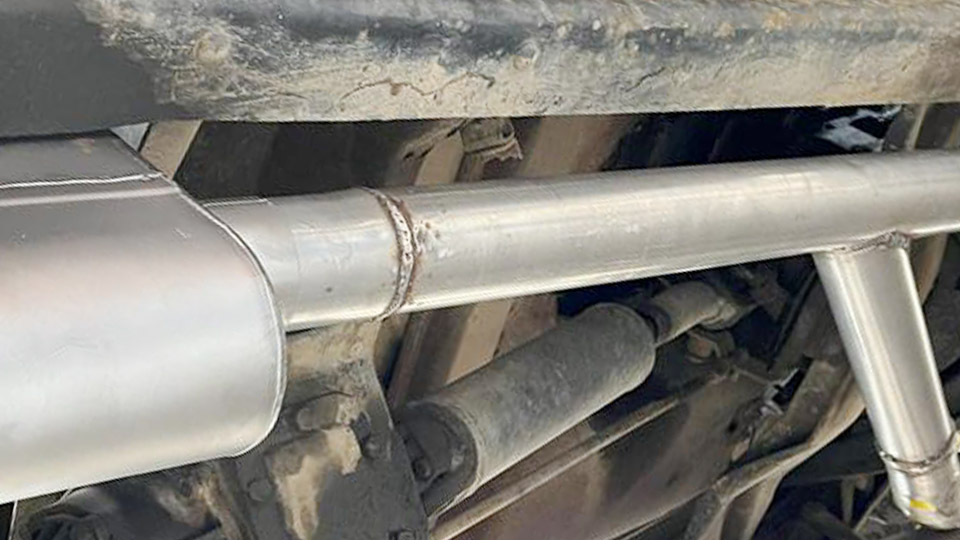
Attempting a direct fusion weld between bronze and steel often ends with cracks, incomplete bonding, or a brittle interface that fails under load.
The core issue is metallurgical incompatibility: bronze melts near 1,650 °F while mild steel remains solid until roughly 2,500 °F, and the two metals show limited mutual solubility plus large differences in thermal expansion and conductivity.
Can you weld bronze to steel successfully? Yes—when the process is selected and controlled to manage heat input, filler metallurgy, and residual stresses rather than forcing full fusion of both base metals.
Choosing the wrong approach wastes material and creates joints that look acceptable until service loads or thermal cycling reveal the defects.
The practical path prioritizes brazing-style techniques with compatible copper-alloy fillers that wet both surfaces without creating harmful intermetallics or excessive distortion.
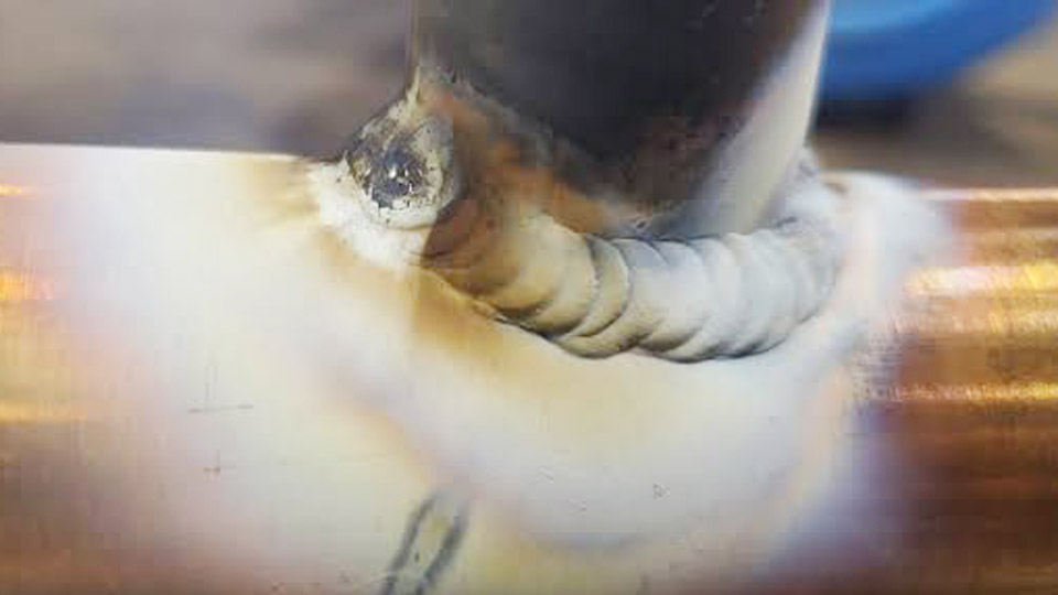
Image by katanakenley
Why Direct Fusion Welding of Bronze to Steel Fails
Melting-Point and Heat-Flow Mismatch
Bronze reaches a fluid state hundreds of degrees before steel begins to melt. Any arc or flame hot enough to produce a steel weld pool overheats the bronze, causing excessive dilution, porosity, and loss of the bronze’s intended properties.
The high thermal conductivity of copper alloys draws heat away rapidly, so the steel side often remains under-heated while the bronze side overheats. The result is incomplete fusion on the steel face and a wide, weak heat-affected zone on the bronze.
Thermal Expansion and Residual Stress
Bronze expands and contracts more than carbon steel during the heating-cooling cycle. When the joint cools, differential shrinkage generates tensile stresses that readily crack the lower-ductility interface or the bronze itself.
Rigid fixturing amplifies the problem; loose or spring-loaded clamping reduces it but cannot eliminate the stress if full fusion has already mixed the metals.
Intermetallic and Embrittlement Risks
Copper has low solubility in iron. Excess mixing forms brittle copper-rich films along steel grain boundaries. Subsequent fusion welding over residual bronze can trigger liquid-metal embrittlement, producing cracks that cannot be repaired by re-welding.
Codes and good practice therefore treat residual copper contamination as a reason to remove material to clean parent metal before any steel fusion weld.
Preferred Joining Processes and When Each Applies
TIG Brazing with Silicon Bronze Filler
TIG (GTAW) with ERCuSi-A or equivalent silicon-bronze rod is the most controllable method for most shop and field work. The process melts only the filler; the steel and bronze surfaces reach wetting temperature without bulk melting.
DCEN polarity, pure argon at 15–20 cfh, and a gas-lens cup produce a stable, oxidizing-free arc. Typical starting currents for 1/16–1/8 in. rod on 1/8 in. stock fall in the 35–75 A range; heavier sections may reach 100–120 A.
Torch angle is kept shallow toward the steel side so the bronze wets the cooler, higher-conductivity steel first. Travel is deliberate and the puddle is kept small to limit heat input. This method suits bearings, light structural attachments, artistic work, and repairs where appearance and minimal distortion matter.
MIG Brazing with Silicon- or Aluminum-Bronze Wire
Pulsed or short-circuit MIG using CuSi-3 or CuAl-type wire deposits filler faster and is practical for production or larger bearing pads. Voltage is set 2–4 V lower and wire-feed speed roughly 15 % slower than comparable steel settings. 100 % argon or argon-helium mixes provide shielding.
The process still avoids full melting of the steel; the filler wets and bonds. It is preferred when adding sacrificial bronze layers to steel components that will later be machined, or when joining thicker sections where TIG travel speed becomes uneconomical. Impact resistance of the deposited pad exceeds that of conventional torch-brazed joints.
Oxy-Acetylene Braze Welding
Torch brazing with fluxed silicon-bronze, phosphor-bronze, or brass rods remains useful for field repairs without electrical power. A neutral to slightly reducing flame brings both surfaces to a dull red (steel) while the filler melts and flows by capillary action or gravity into a prepared joint.
Flux must be applied thoroughly to remove oxides. Heat input is higher than TIG, so distortion risk rises on thin sections, but the method works well on thicker cast or wrought parts when careful preheating equalizes temperatures.
Overlay and Buttering Sequences for Higher Strength
When a fusion-like bond or thick bronze build-up is required, the steel surface is first buttered with a thin layer of silicon or aluminum bronze using TIG or MIG. After cleaning, subsequent passes build the bronze thickness.
For aluminum bronze to steel, matching aluminum-bronze electrodes or wires (ERCuAl-A2 class) are used; preheat of 300–400 °F on thicker steel sections improves wetting.
Nickel-based intermediate layers are occasionally applied when copper dilution into steel must be strictly limited, but they add cost and complexity.
Joint Design and Preparation Decisions That Control Success
Fit-Up and Clearance Requirements
Brazing-style joints need controlled clearance—typically 0.002–0.006 in. for capillary flow—or a slight bevel that allows the filler to wet both faces without large gaps. Butt joints on thicker material benefit from a modest V-groove so the filler can be deposited in layers.
Overly tight or zero-clearance fits prevent proper flow; excessive gaps force the operator to bridge with multiple passes and raise heat input.
Surface Cleaning and Oxide Control
Both metals must be free of oil, scale, paint, and oxide. Steel is ground or wire-brushed to bright metal; bronze is cleaned with stainless brushes or chemical methods that avoid embedding iron particles.
Residual oxides on aluminum bronze are especially tenacious and require mechanical removal plus effective shielding or flux. Contaminated surfaces produce porosity and lack of wetting even when amperage and technique are correct.
Preheating and Interpass Temperature Limits
Steel thicker than approximately 3/16 in. benefits from preheat to 250–350 °F so it reaches wetting temperature at the same time as the bronze. Excessive preheat on the bronze side is avoided because it accelerates oxidation and grain growth.
Interpass temperature is kept low enough that the previously deposited bronze remains solid; rapid cooling under restraint is also avoided by covering the joint or using sequential balanced welding.
Machine Settings and Process Variables That Determine Bond Quality
TIG Parameter Windows
For ERCuSi-A 1/16 in. rod on light plate: 30–50 A DCEN, 100 % argon 12–18 cfh, 1/16 in. lanthanated tungsten, #6–#8 gas lens. On 1/8 in. material the range rises to 55–80 A.
Arc length is held short; the filler is dabbed into the leading edge of a small puddle rather than held continuously in the arc. Travel speed is adjusted so the bronze wets both faces without undercutting the steel.
MIG Parameter Adjustments Relative to Steel
0.030–0.035 in. silicon-bronze wire typically runs at lower voltage and reduced wire speed compared with ER70S-6 on the same thickness. Short-circuit or pulsed modes minimize spatter and heat. Stick-out is kept short (⅜ in. or less). Push angle of 10–15° helps the fluid bronze wet the joint ahead of the arc.
Filler Selection by Alloy Type
Silicon bronze (ERCuSi-A) is the most forgiving for general bronze-to-steel work and gives a gold-colored, corrosion-resistant deposit. Aluminum bronze fillers provide higher strength and better wear resistance for bearing overlays but demand better oxide control and often AC or specialized DC techniques on aluminum-bearing alloys.
Phosphor-bronze fillers suit tin-bronze base metals. Matching the major alloying element of the bronze component reduces dilution problems.
Strength, Service Limits, and Inspection Criteria
Load-Carrying Capacity of Brazed Versus Fusion Joints
A properly executed silicon-bronze TIG or MIG braze develops shear and compressive strength adequate for most non-critical structural and mechanical applications. Tensile strength across the joint is lower than a matched steel weld but often exceeds the strength of the bronze itself.
High cyclic tensile or impact loads may require redesign to place the joint in shear or the addition of mechanical fasteners. Bearing pads deposited by MIG bronze overlay routinely outlast pressed or brazed liners under sliding wear.
Corrosion and Galvanic Considerations
The copper-steel interface creates a galvanic couple in electrolyte environments. Silicon bronze is relatively noble; the steel may corrode preferentially if the joint is exposed.
Protective coatings, isolation, or design that keeps the joint dry mitigate the risk. Marine and chemical service often favor aluminum bronze for its superior corrosion performance.
Visual and Non-Destructive Acceptance
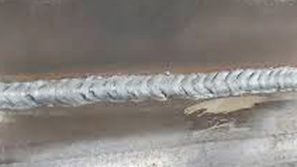
A sound joint shows continuous wetting along both toes, a smooth concave or slightly convex profile, and no porosity or undercut. Dye-penetrant or magnetic-particle inspection (on the steel side) detects surface cracks.
For critical work, sectioning of process-qualification samples verifies the absence of intermetallic films and adequate bond line.
Decision Framework for Selecting the Correct Approach
Evaluate the required mechanical performance first. Light loads, appearance-critical, or thin-section work point to TIG silicon-bronze brazing. Production volume or thick bronze overlays favor pulsed MIG. Field repairs without power use oxy-acetylene.
High-strength or wear applications may need aluminum-bronze buttering plus multi-pass build-up. Always verify cleaning, fit-up, and heat balance on scrap of identical thickness and alloy before committing to the production joint.
When residual bronze must later receive a steel fusion weld, remove all copper alloy to clean parent metal; otherwise liquid-metal embrittlement is likely.
Wrapping Up
Successful bronze-to-steel joints depend less on maximum amperage or exotic equipment than on deliberate heat management and filler choice that respects the physical differences between the metals.
Operators who treat the process as controlled wetting rather than conventional fusion consistently produce serviceable results across bearings, repairs, and fabricated assemblies.
Advanced practice further refines residual-stress control by sequencing deposits from the higher-conductivity side and allowing intermediate cooling under reduced restraint, preserving joint integrity under thermal cycling that would crack a conventionally fusion-welded interface.
FAQs
Can you TIG weld bronze directly to mild steel?
Yes, using silicon-bronze filler in a brazing mode (DCEN, pure argon, low amperage). The filler melts and wets both surfaces without bulk melting of the steel.
What filler rod works best for bronze to steel?
ERCuSi-A silicon bronze is the most versatile for general TIG and MIG work. Aluminum-bronze fillers (ERCuAl-A2) are chosen when higher strength or wear resistance is required.
Is bronze-to-steel stronger than a regular steel weld?
In pure tensile pull a matched steel weld is stronger, but a properly made silicon-bronze braze provides adequate shear and compressive strength for most mechanical and light structural uses while avoiding the cracking risks of fusion.
Can MIG be used to join bronze to steel?
Yes—MIG brazing with silicon- or aluminum-bronze wire in short-circuit or pulsed mode deposits filler that bonds to both metals at lower heat input than steel MIG settings.