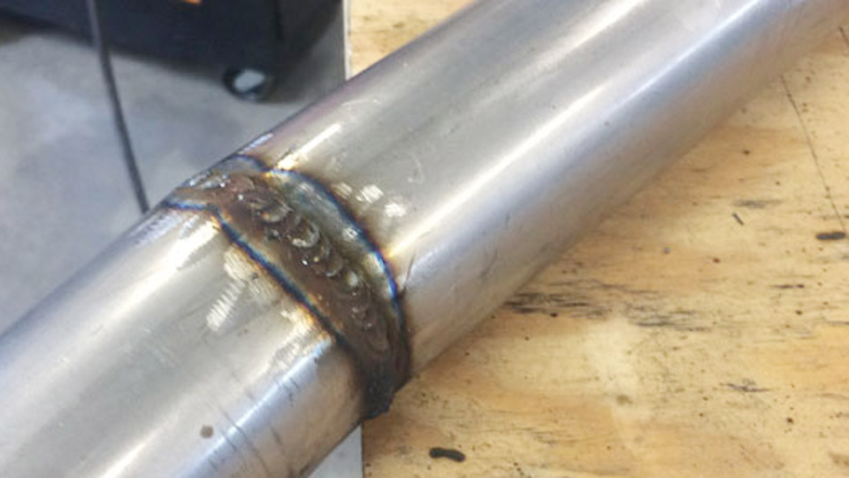
MIG welding car panels requires precise heat control because automotive sheet metal is thin enough to burn through, warp, or develop excessive weld distortion in seconds.
Knowing how to MIG weld car panels helps you create strong, clean joints while preserving the panel’s shape and minimizing grinding during finishing. Unlike welding thicker steel, automotive panel repair demands careful control of voltage, wire feed speed, travel speed, and weld spacing.
Excessive heat can stretch the metal, causing oil-canning and uneven surfaces that are difficult to correct. The right setup also depends on sheet thickness, joint design, wire diameter, and shielding gas.
Whether you’re patching a rust hole, joining a replacement panel, or repairing a damaged body section, understanding these variables helps you achieve consistent welds without unnecessary rework.
Proper preparation and a controlled welding technique are essential for producing durable repairs with a smooth, professional finish.
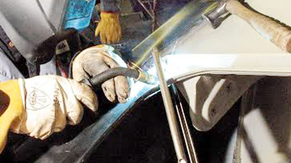
Image by hemmings
Wire, Gas, and Polarity Choices That Match Body-Panel Thickness
Thin automotive steel demands a filler and shielding combination that melts at low amperage while still wetting both edges of the joint.
Why 0.023-Inch ER70S-6 Wire Is the Default
0.023-inch (0.6 mm) solid ER70S-6 wire requires less energy to maintain a stable short-circuit arc than 0.030-inch wire. The smaller diameter produces a tighter puddle that freezes faster, reducing the risk of melt-through on 20- and 22-gauge skins.
ER70S-6 contains enough manganese and silicon deoxidizers to handle light residual mill scale or surface contamination common on used panels. Move to 0.030-inch only when the panel reaches 18 gauge or thicker and the joint geometry needs higher deposition without raising voltage excessively.
C25 Shielding Gas and Flow Rates
75 % argon / 25 % CO₂ (C25) stabilizes the short-circuit arc, limits spatter, and supplies moderate penetration without the aggressive dig of straight CO₂. Set flow between 15 and 25 CFH depending on nozzle size and draft conditions.
Higher flow creates turbulence that pulls air into the puddle and produces porosity; lower flow leaves the weld unprotected at the edges. Pure CO₂ increases penetration and spatter and is rarely the first choice for visible exterior panels.
Polarity and Stick-Out Limits
Run electrode-positive (DCEP). Stick-out of ¼ to ⅜ inch keeps resistance low and arc length predictable. Extending stick-out beyond ½ inch cools the arc but risks instability and increased spatter on thin material.
Voltage and Wire-Speed Windows by Gauge
Machine charts give starting points; the final settings are confirmed on scrap of identical thickness and joint type.
22-Gauge and 20-Gauge Starting Ranges
For 22-gauge (approximately 0.030 inch) with 0.023-inch wire and C25 gas, begin at 13–15 V and 90–130 IPM. On 20-gauge (0.036 inch) raise to 15–16 V and 120–150 IPM. The arc should produce a rapid, crisp sizzle.
A soft hiss indicates excess voltage; a popping or stubbing sound signals insufficient voltage or wire speed. Adjust in 0.5 V or 10 IPM increments until the puddle wets both edges without dropping through.
18-Gauge and Slightly Heavier Panels
18-gauge (0.047 inch) accepts 16–17 V and 140–180 IPM with either 0.023- or 0.030-inch wire. At this thickness a slightly longer stick-out or a brief pause at the edges of a short stitch helps ensure fusion without undercut. Always verify the combination on a test coupon clamped in the same orientation as the actual joint.
Interpreting Arc Sound and Puddle Behavior
A correctly tuned short-circuit arc on body panels sounds like continuous bacon frying. The puddle should remain small, roughly the diameter of a pencil eraser, and travel at a speed that leaves a slightly convex bead with clean toes.
If the edge melts back faster than the filler can fill it, drop voltage first. If the bead sits high and fails to fuse, increase voltage or slow travel slightly while keeping the trigger bursts short.
Joint Fit-Up Decisions: Butt Versus Lap on Exterior and Structural Panels
The joint design controls both final appearance and corrosion resistance.
Butt Joint Requirements for Visible Skins
Exterior door skins, quarter panels, and fenders are normally repaired with butt joints. Maintain a gap no wider than the wire diameter so the edges can fuse with minimal filler. Larger gaps force additional heat and increase distortion.
Clamp or cleco the patch so both surfaces remain flush and coplanar; any step or gap variation concentrates heat on the higher edge and produces burn-through. After tacking, the seam should present a continuous, even line ready for short stitches.
When Lap Joints Are Acceptable
Lap joints appear on flanges, inner structures, floor pans, and areas that will be fully sealed. They are more tolerant of imperfect cuts but create a moisture trap between the overlapping layers. Apply weld-through primer only where the repair procedure permits, and seal the finished joint thoroughly.
Never use an open lap on a visible outer panel that will see weather exposure without complete corrosion protection.
Gap Control and Edge Preparation
Remove paint, undercoating, sealer, and rust to bare metal for at least ½ inch on both sides of the joint. Deburr edges so they seat tightly. On butt joints a slight edge bevel is unnecessary and can widen the gap; square, clean edges give the most consistent fusion on thin steel.
Heat-Input Control That Prevents Warping and Burn-Through
Thin sheet expands and contracts rapidly. Total heat input, not peak amperage alone, determines whether the panel remains flat.
Short Trigger Bursts and Cooling Intervals
Limit each weld to ½–1 second of arc time. After every few tacks, move to a distant section of the seam or the opposite side of the panel. Allow the metal to cool until it is only warm to the touch before returning.
Compressed air can accelerate surface cooling, but do not quench so aggressively that residual stresses are locked in. Continuous beads of any length are the primary cause of oil-canning and panel distortion.
Skip and Stitch Sequencing
Place the first series of tacks every 1–2 inches along the entire seam to lock geometry. Then fill the spaces by working in a staggered pattern—never consecutive sections.
This distributes shrinkage evenly and keeps any single area from becoming a heat sink. On large panels such as roofs or hoods the same principle applies: complete one quadrant, cool, then move to the opposite quadrant.
Copper Backing and Heat Sinks
When access permits, place a copper or brass bar directly behind the joint. Copper does not fuse to the steel and draws heat away from the puddle, supporting the molten metal and reducing the chance of melt-through. Remove the bar after the seam is complete.
Clamping the panel to a heavy fixture or using magnetic heat sinks on the opposite side of the skin further limits local temperature rise.
Plug-Weld and Panel-Replacement Sequences
Most factory panel attachments use resistance spot welds. Replacement panels are commonly secured with MIG plug welds that replicate the original load path.
Hole Size and Location
Drill or punch 5/16- to ⅜-inch holes in the new panel at the original spot-weld locations or according to the vehicle maker’s repair procedure. Clean both mating surfaces and apply weld-through primer only if specified. Clamp the panels tightly so the inner structure contacts the outer panel through the hole.
Filling Technique
Position the gun perpendicular to the hole, establish the arc on the inner panel, and fill outward in a continuous circular motion until the hole is closed and the bead is slightly proud.
Keep the arc time short; multiple short fills with cooling are safer than one long fill that overheats the surrounding skin. Grind the finished plug flush only after the area has cooled.
Structural Versus Cosmetic Considerations
On non-structural outer skins the primary goals are fusion, minimal distortion, and a finishable surface. On structural members, rocker panels, or pillars follow the OEM procedure exactly—many modern high-strength steels prohibit MIG welding or require specific wire, gas, and heat-input limits. Ignoring those limits can compromise crash performance.
Diagnosing and Correcting Common Problems on Thin Steel
Most defects announce themselves immediately through arc behavior or bead appearance.
Burn-Through and Edge Melt-Back
Reduce voltage 0.5–1 V, shorten the trigger burst, increase travel speed, or add copper backing. Verify that the gap is not excessive; a wide gap forces the arc to dwell longer while bridging.
Cold Lap and Lack of Fusion
Raise voltage slightly or reduce travel speed so the puddle wets both edges. Confirm that the metal is clean and the ground clamp is attached to bare steel close to the weld. A ropey, high bead that sits on the surface rather than sinking into the joint indicates insufficient energy.
Porosity and Spatter
Check gas flow, nozzle condition, and stick-out. Contaminated metal or a draft that blows the shielding gas away are common causes. Excessive voltage or wire speed also increases spatter; return to the tested short-circuit range.
Residual Distortion After Welding
Planish the weld line with a hammer and dolly while the metal is still slightly warm to stretch the shrunken zone. Avoid aggressive grinding that further heats the panel. If oil-canning remains, controlled heating and shrinking with a torch or inductive heater can restore shape, but prevention through proper sequencing is far more efficient.
Wrapping Up
The combination of 0.023-inch ER70S-6 wire, C25 gas, short-circuit parameters in the 13–17 V range, and disciplined skip-stitch sequencing produces reliable fusion on automotive sheet metal while preserving panel contour. Test every parameter combination on scrap of the same gauge and joint type before touching the vehicle.
Once the arc sound, puddle size, and bead profile are confirmed, the same settings transfer directly to the repair.
Advanced operators further refine heat input by pairing short stick-out with deliberate back-stepping on long seams, ensuring that residual stresses remain low enough for the panel to stay flat through finishing and years of service.
FAQs
What wire size should I use for MIG welding car body panels?
0.023-inch or 0.024-inch ER70S-6 solid wire is the preferred choice for 18- to 22-gauge panels because it runs at lower heat and produces a controllable short-circuit arc.
How do I stop car panels from warping when MIG welding?
Use short ½- to 1-second tacks, skip around the seam, allow full cooling between welds, maintain tight fit-up, and avoid any continuous bead longer than one inch.
What voltage and wire speed work for 20-gauge auto body steel?
Start at 15–16 V and 120–150 IPM with 0.023-inch wire and C25 gas, then fine-tune on scrap until the arc produces a tight, wetting puddle without melt-through.
Can I use flux-cored wire for welding thin car panels?
Self-shielded flux-cored wire runs hotter and produces more spatter and slag; gas-shielded solid wire with C25 is cleaner and easier to control on exterior body panels.