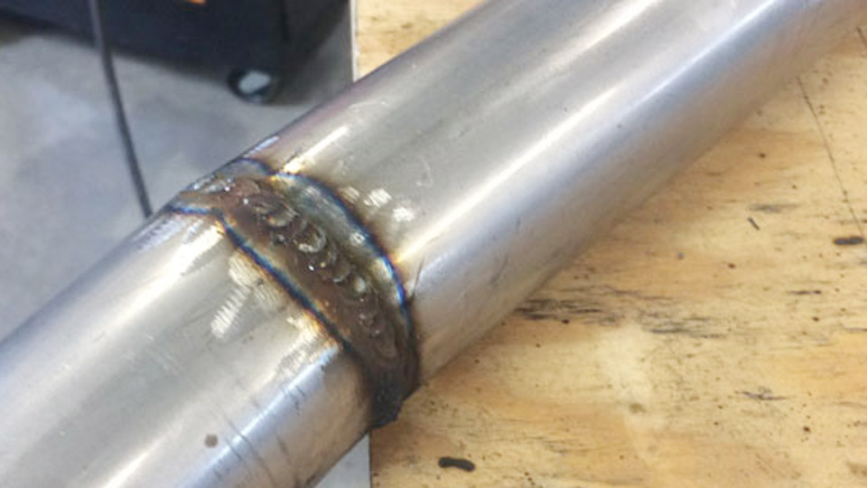
Incorrect MIG welding parameters can cause poor penetration, excessive spatter, burn-through, or inconsistent weld beads, even when your technique is sound.
Knowing how to set MIG welding parameters helps you match voltage, wire feed speed, travel speed, and shielding gas to the metal thickness, wire diameter, and joint configuration.
These settings work together: voltage influences arc length and bead profile, while wire feed speed largely controls welding current and deposition rate. An imbalance between them can produce an unstable arc, poor fusion, or unnecessary cleanup and rework.
Whether you’re welding thin sheet metal, joining mild steel plate, or working on a fabrication project, selecting the right starting settings is essential for consistent results.
Understanding how each parameter affects the weld will help you make controlled adjustments, evaluate bead quality, and achieve reliable fusion without relying entirely on trial and error.
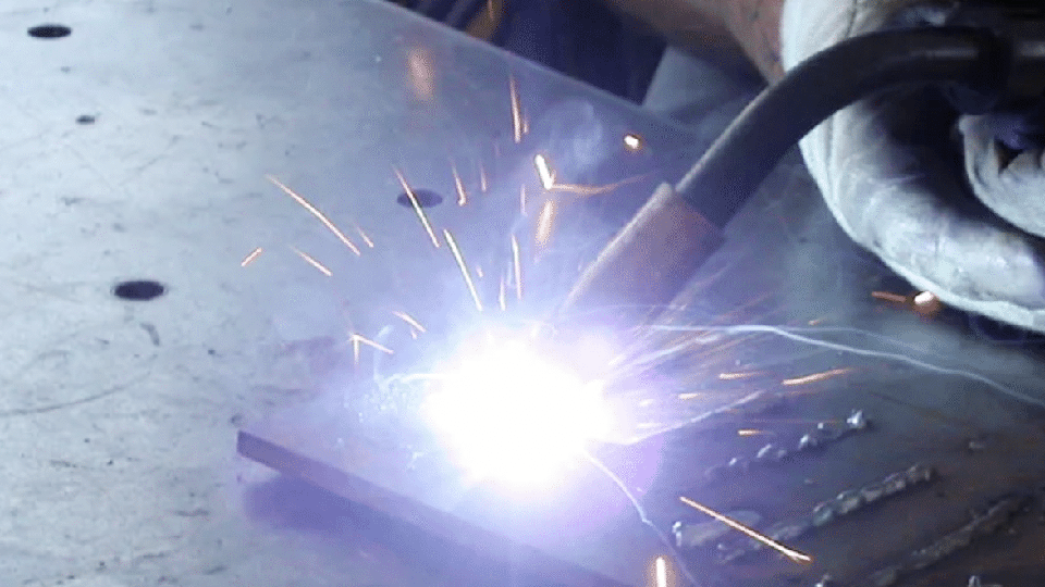
Image by zintilon
Choosing Wire Diameter and Target Amperage First
Wire diameter and the resulting amperage range must match the thickness being welded before any voltage or feed-speed dial is touched.
Thickness-to-Amperage Rule for Mild Steel
A practical starting point for short-circuit transfer on carbon steel is approximately 1 amp per 0.001 inch of material thickness. A 1/8-inch (0.125-inch) plate therefore targets roughly 125 A. Thinner sheet (16–18 gauge) falls in the 60–100 A band; 3/16-inch material moves toward 150–180 A.
This rule applies primarily to solid ER70S-6 wire in the short-circuit mode and assumes good fit-up and flat or horizontal position.
Matching Wire Size to the Amperage Window
Miller and Lincoln guidelines assign typical operating ranges by diameter:
- 0.023-inch wire: 30–130 A
- 0.030-inch wire: 40–145 A
- 0.035-inch wire: 50–180 A
- 0.045-inch wire: 75–250 A
Select the diameter that places the calculated amperage comfortably inside its range rather than at the extreme edge. Using 0.035-inch wire for most 1/8-inch to 3/16-inch work keeps the machine in a stable portion of its output curve and reduces the need for frequent spool changes.
Calculating and Setting Wire Feed Speed
Wire feed speed (WFS) directly controls amperage because the constant-voltage power source burns off the wire at the rate it is fed.
Manufacturer Multipliers for Solid Steel Wire
Once target amperage is known, convert it to inches per minute with these multipliers:
- 0.023-inch: 3.5 ipm per amp
- 0.030-inch: 2.0 ipm per amp
- 0.035-inch: 1.6 ipm per amp
- 0.045-inch: 1.0 ipm per amp
Example: 125 A on 0.035-inch wire yields approximately 200 ipm (125 × 1.6). Start at that value and refine on scrap.
Practical WFS Ranges by Thickness (ER70S-6, C25 Gas)
| Material Thickness | Wire Diameter | Approximate WFS (IPM) | Approx. Amperage |
|---|---|---|---|
| 18–16 ga | 0.030″ | 120–200 | 60–100 A |
| 14 ga–1/8″ | 0.035″ | 180–260 | 110–160 A |
| 3/16″ | 0.035″ | 225–300 | 140–180 A |
| 1/4″ (short-circuit) | 0.035″ | 245–300 | 155–180 A |
| 1/4″+ (spray) | 0.045″ | 310–400 | 260–320 A |
These figures assume DCEP polarity and 75 % argon / 25 % CO₂. Actual machine output and stick-out length shift the numbers slightly.
Setting Voltage to Stabilize the Arc
Voltage controls arc length and therefore bead shape. It must stay in balance with the chosen wire feed speed.
Voltage Windows for Short-Circuit Transfer
Short-circuit transfer on mild steel with C25 gas typically runs between 16 V and 22 V. Lower voltages produce a taller, narrower bead and a harsher arc; higher voltages flatten the bead and increase the risk of undercut or porosity. For 1/8-inch material a common starting band is 18–21 V paired with the WFS calculated above.
Recognizing Correct Voltage by Arc Sound and Bead Profile
A properly balanced setting produces a steady, crisp crackling sound similar to frying bacon. If the wire repeatedly stubs into the work, voltage is too low relative to WFS—raise voltage in 0.5 V increments.
If the arc becomes long, erratic, and spatters heavily, lower voltage or increase WFS slightly. The finished bead should show good toe fusion without excessive reinforcement or undercut.
Selecting Shielding Gas and Flow Rate
Gas composition and flow rate determine transfer mode capability and weld-pool protection.
Gas Choices for Carbon Steel
- 75 % argon / 25 % CO₂ (C25): most common for short-circuit transfer; good arc stability and moderate penetration.
- 90 % argon / 10 % CO₂ or higher argon mixes: required to reach true axial spray transfer.
- 100 % CO₂: deeper penetration and higher deposition but more spatter; often needs 1–2 V higher settings.
Flow rates of 20–35 CFH cover most indoor short-circuit work. Increase toward 35–45 CFH for spray transfer or when draft is present. Excess flow creates turbulence that pulls air into the shield and produces porosity.
Stick-Out (Contact-Tip-to-Work Distance) Effects
Short-circuit transfer works best with ¼–½ inch stick-out. Longer stick-out increases resistance, effectively lowering amperage and raising the risk of porosity. Spray transfer tolerates ½–¾ inch stick-out. Maintain consistent distance; varying stick-out changes the effective parameters even if the dials remain fixed.
Short-Circuit Versus Spray Transfer Decisions
Transfer mode is governed by voltage, current, gas, and position.
When Short-Circuit Is the Correct Choice
Short-circuit transfer operates at lower heat input and works in all positions. It is the default for sheet metal through roughly 3/16-inch plate and for any out-of-position work. The wire touches the puddle 90–200 times per second, producing the characteristic crackling sound. Use C25 gas and stay below the spray-threshold amperage for the chosen wire diameter.
Conditions Required for Spray Transfer
Axial spray requires higher current (typically above 175–220 A depending on wire size), higher voltage (24–30 V), and argon-rich gas (≥80–90 % argon). It produces a smooth, quiet arc with fine droplet transfer, high deposition, and excellent wetting, but is limited to flat and horizontal positions.
On ¼-inch and thicker plate, spray with 0.045-inch wire often delivers single-pass fillet capability that short-circuit cannot match.
Adjusting Parameters for Position and Joint Type
Position and joint geometry alter heat input requirements.
Vertical and Overhead Reductions
Reduce wire feed speed (and therefore amperage) 10–15 % from the flat-position value and drop voltage slightly. The colder puddle freezes faster and resists sagging. Maintain a short arc and use a slight weave or triangle technique on vertical-up fillets.
Fillet Versus Groove Joint Considerations
Fillet welds on clean material often run successfully at the mid-range of the thickness chart. Open-root or beveled groove joints may need 5–10 % higher amperage or a slight increase in voltage to ensure root fusion. Always verify penetration by sectioning a test coupon when full penetration is required.
Fine-Tuning Sequence on Scrap
A systematic adjustment sequence produces repeatable results faster than random dial turning.
Order of Adjustment
- Select wire diameter and set calculated WFS for the target amperage.
- Set voltage in the middle of the expected band for that thickness and transfer mode.
- Establish correct stick-out and travel speed on scrap of identical thickness and joint geometry.
- Listen for the steady crackling arc and observe bead shape.
- Raise or lower voltage in 0.5 V steps until the arc stabilizes; then make final small WFS corrections if needed.
- Record the final voltage, WFS, gas flow, and stick-out for that material and machine combination.
Travel speed interacts with the electrical parameters. Faster travel reduces heat input and reinforcement height; slower travel increases penetration and bead width. Keep travel consistent once the electrical settings are locked.
Common Parameter Interactions That Change Results
Several secondary variables shift the effective operating point even when dial settings remain unchanged.
Machine Output and Cable Length
Voltage drop in long or undersized work leads and electrode cables lowers actual arc voltage. Compensate by raising the machine voltage setting or shortening the leads. Inverter machines often deliver more stable arcs at the lower end of a given range than older transformer machines.
Surface Condition and Fit-Up
Mill scale, rust, or oil requires higher heat input or thorough cleaning. Tight fit-up with zero root gap may demand slightly higher amperage for fusion; large gaps increase the risk of burn-through and may need lower settings plus filler-metal technique adjustments.
Wrapping Up
Correct MIG parameter selection rests on matching thickness to amperage, converting that amperage into the proper wire feed speed for the chosen diameter, and balancing voltage so the arc remains short and stable.
Charts supply the starting numbers; the final values come from observing arc sound, bead profile, and penetration on scrap that matches the production joint.
Once those values are recorded for a given machine, wire, and gas combination, subsequent jobs of the same thickness require only minor position or travel-speed compensation.
Advanced operators further refine heat input by controlling stick-out consistency and by switching deliberately between short-circuit and spray regimes rather than forcing one mode across every thickness.
FAQs
What voltage and wire speed for 1/8-inch mild steel MIG?
Start near 19–21 V and 210–260 IPM with 0.035-inch ER70S-6 wire and C25 gas for short-circuit transfer. Fine-tune on scrap until the arc sounds steady and the bead shows good fusion.
How do I calculate MIG wire feed speed from amperage?
Multiply target amperage by the wire-diameter factor: 2.0 for 0.030-inch, 1.6 for 0.035-inch, or 1.0 for 0.045-inch wire. Example: 125 A × 1.6 ≈ 200 IPM on 0.035-inch wire.
When should I use spray transfer instead of short-circuit?
Use spray on ¼-inch and thicker material in the flat or horizontal position when argon-rich gas and sufficient machine output (typically >200 A) are available. It delivers higher deposition and smoother beads but cannot be used out of position.
What gas flow rate for MIG welding mild steel?
20–35 CFH of C25 covers most short-circuit work indoors. Raise flow to 35–45 CFH for spray transfer or when drafts are present. Excess flow causes turbulence and porosity.