
Incomplete fusion on one side of a butt joint and burn-through on the other usually trace to mismatched laser welding parameters. Power that is too low relative to travel speed leaves a shallow keyhole or pure conduction-mode weld; power that is too high for the same speed produces excessive vaporization, porosity, and undercut.
Focus offset, spot diameter, and shielding gas flow further decide whether the energy couples efficiently or reflects away.
Correct parameter sets deliver deep, narrow penetration with minimal heat-affected zone and distortion—exactly why fabricators choose laser over arc processes for thin-to-medium gauge work. Getting the combination right on the first test coupon saves scrap, rework, and certification failures.
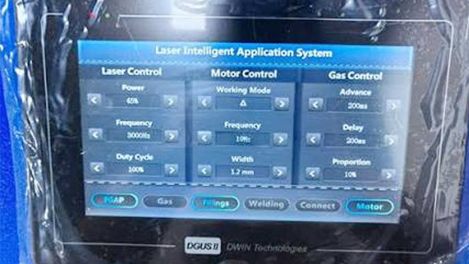
Image by raymaxlaser
How Power and Travel Speed Determine Penetration Depth
Laser power and travel speed form the primary energy-input pair. Their ratio, heat input in J/mm, must stay inside a narrow window for each material and thickness.
Calculating Useful Heat Input
Heat input is expressed as
[ H = \frac{P}{v} ]
where ( P ) is laser power in watts and ( v ) is travel speed in mm/s (or convert consistently). For mild and stainless steel the practical window is roughly 20–80 J/mm; aluminum often needs 50–150 J/mm because of higher reflectivity and thermal conductivity.
Below the lower limit the keyhole collapses and penetration falls short. Above the upper limit the heat-affected zone widens, distortion rises, and porosity increases.
Keyhole Threshold and Minimum Power Density
Keyhole welding requires power density above approximately ( 10^6 ) W/cm². A 1 500 W fiber laser focused to a 0.3 mm diameter spot easily exceeds this value. Conduction-mode welding occurs at lower densities and produces wider, shallower beads useful only for cosmetic or very thin work.
Once the keyhole threshold is crossed, penetration depth scales roughly with power divided by speed, provided the focus remains near the surface.
Practical Power–Speed Windows for Steel
On mild or carbon steel a 1 500 W system typically runs:
- 0.5–1.0 mm sheet: 500–1 000 W at 2.0–3.5 m/min
- 1.5–2.0 mm: 1 000–1 400 W at 1.2–2.5 m/min
- 3.0–4.0 mm: full 1 500 W at 0.6–1.5 m/min
Higher-power machines (2–3 kW) allow the same thicknesses at correspondingly higher speeds or extend single-pass capability to 6–8 mm.
Focus Position and Spot Size Choices That Change Energy Distribution
Focus offset and focused spot diameter control where the peak power density sits relative to the joint and how the energy is distributed through the thickness.
Surface Focus versus Positive or Negative Offset
For carbon steel and stainless steel the focal plane is normally set at or just below the top surface (0 to –1 mm). Negative offset places the waist of the beam inside thicker sections and increases penetration.
Aluminum requires the opposite: +3 to +5 mm positive focus softens the keyhole entrance, reduces spatter, and lowers the chance of burn-through on thin sheet. A 1 mm focus error that is tolerable on steel often produces porosity or incomplete fusion on aluminum.
Spot Diameter Trade-offs
Typical focused spot diameters for fiber-laser welding range from 0.2 mm to 0.6 mm. Smaller spots raise power density and produce narrow, deep keyholes ideal for full-penetration butt joints. Larger spots lower density, widen the weld, and improve gap-bridging or cosmetic appearance.
Changing collimation or focusing optics alters spot size; most production systems keep a fixed optic set and adjust power and speed instead.
Rayleigh Length and Thickness Limits
A longer Rayleigh length (depth of focus) maintains usable power density through thicker sections. High-beam-quality single-mode fiber lasers keep the Rayleigh length several millimetres long, supporting single-pass welds up to 6–10 mm when power is sufficient. Multi-mode beams with higher BPP require more power or multi-pass strategies for the same thickness.
Material-Specific Starting Parameters for Common Thicknesses
Parameter tables must be material-specific because absorption, conductivity, and oxide behaviour differ sharply.
Mild and Carbon Steel Reference Settings
On a 1.5–2 kW fiber system with nitrogen or argon shielding at 15–20 L/min and focus at surface:
| Thickness (mm) | Power (W) | Travel Speed | Notes |
|---|---|---|---|
| 0.5–1.0 | 500–1 000 | 2.0–3.5 m/min | Autogenous preferred |
| 1.5–2.0 | 1 000–1 500 | 1.2–2.5 m/min | Wire optional for gap fill |
| 3.0–4.0 | 1 500–2 500 | 0.8–1.5 m/min | Full penetration single pass |
Carbon steel tolerates slightly higher power than stainless for the same thickness because of better absorption once the keyhole forms.
Stainless Steel Adjustments
Stainless (304/316) runs at 10–15 % lower power than mild steel for equivalent penetration or at the same power with slightly higher speed. Argon or nitrogen shielding at 12–20 L/min prevents oxidation and keeps the bead bright.
Autogenous welding is preferred below 1.5 mm; filler wire (ER308L or ER316L) becomes useful above 2 mm for gap bridging and bead profile control.
Aluminum Alloy Requirements
Aluminum (5xxx/6xxx series) demands 1.5–3 times the power of steel at the same thickness and positive focus offset. Typical 2 kW settings:
| Thickness (mm) | Power (W) | Travel Speed | Focus Offset | Wire Feed (if used) |
|---|---|---|---|---|
| 1.0 | 1 000–1 500 | 1.8–3.0 m/min | +3 mm | 1.0 mm at 12–15 mm/s |
| 1.5–2.0 | 1 500–2 500 | 1.2–2.0 m/min | +3 to +5 mm | 1.2–1.6 mm at 10–13 mm/s |
Nitrogen or helium–argon mixes at ≥20 L/min are essential to suppress porosity. Surface cleaning and tight fit-up are non-negotiable.
Shielding Gas Selection and Flow Rates That Control Defects
Gas choice and delivery directly affect porosity, oxidation, and keyhole stability.
Argon, Nitrogen and Helium Roles
Argon is the default for stainless and mild steel; it is inexpensive and provides good coverage. Nitrogen is preferred on many handheld systems for both steel and aluminum because it produces cleaner surfaces and reduces cost.
Helium or helium–argon mixes raise plasma ionization potential, improve energy coupling on aluminum and copper, and reduce porosity on thicker stainless, but they raise operating cost.
Flow rates of 12–25 L/min measured at the nozzle are typical; insufficient flow allows atmospheric contamination while excessive flow can disturb the keyhole.
Delivery Geometry and Trailing Shields
Coaxial or off-axis nozzles must maintain laminar flow over the weld pool for several millimetres behind the keyhole. On reactive alloys or thick sections a trailing shield or gas knife extends coverage and prevents oxidation of the cooling bead. Gas purity ≥99.99 % is required; moisture or oxygen contamination immediately produces porosity.
Handheld Systems: Wobble, Peak Power Percentage and Wire Feed
Handheld fiber lasers introduce oscillation (wobble) and percentage-based power settings that differ from fixed-optic industrial systems.
Peak Power Percentage and Scan Parameters
On a 1 200–2 000 W handheld unit the controller often displays peak power as a percentage of rated output. Typical stainless and carbon-steel starting points:
- 0.8–1.2 mm: 30–45 % peak power, scan width 2.5–3.0 mm, frequency 60–100 Hz
- 2.0–3.0 mm: 45–70 % peak power, scan width 3.5–4.5 mm, frequency 30–40 Hz
Wobble width increases bead width and gap tolerance; frequency controls energy distribution along the weld path. Lower frequency on thicker material increases energy per oscillation cycle.
Wire-Feed Coordination
When filler is required, wire diameter is matched to thickness (0.8–1.6 mm) and feed speed is set so the wire melts fully without stubbing or excessive build-up. Typical feed rates fall between 8–18 mm/s. Wire must enter the leading edge of the keyhole or pool; misalignment produces lack of fusion or cold wire defects.
Diagnosing Parameter-Related Defects from Bead Appearance
Visual and metallographic clues point directly to which parameter is out of balance.
Porosity and Incomplete Penetration
Porosity usually indicates insufficient shielding, excessive power that creates turbulent vapor, or positive focus that is too high on steel. Incomplete penetration is corrected by raising power, lowering speed, or moving focus slightly negative. Cross-sectioning a test coupon remains the fastest verification method.
Undercut, Spatter and Excess Reinforcement
Undercut and heavy spatter appear when power density is too high relative to travel speed or when the beam is angled excessively. Excess reinforcement or convexity often results from too much wire feed or travel speed that is too low. Reducing peak power 5–10 % or increasing speed restores balance.
Distortion and Heat-Affected Zone Width
Wide HAZ and visible distortion signal excessive heat input. The remedy is higher speed at the same power or a reduction in power while maintaining the required penetration. Pulsed or modulated waveforms further limit average heat input on thin or heat-sensitive parts.
Wrapping Up
Selecting the correct laser welding parameters is a sequential decision: first establish the power–speed pair that delivers the required penetration and heat-input window, then set focus offset for the material, then lock shielding gas and any wobble or wire-feed values.
Test coupons of the actual alloy and joint geometry remain essential because surface condition, fit-up gap, and machine calibration shift the optimum set-points.
Advanced operators further refine performance by recording actual delivered power (not just set-point percentage) and by using real-time keyhole monitoring or post-weld metallography to confirm process windows for production certification.
FAQs
What laser power is needed for 2 mm stainless steel?
A 1 200–1 800 W fiber laser at 1.5–2.5 m/min typically produces full-penetration butt welds on 2 mm 304/316 with argon or nitrogen shielding and focus at the surface.
What travel speed should I use for 1 mm aluminum laser welding?
Start at 1.8–3.0 m/min with 1 000–1 500 W, positive focus (+3 mm), and nitrogen or helium–argon shielding at ≥20 L/min; adjust after cross-section checks.
How does focus position differ between steel and aluminum?
Steel uses 0 to –1 mm (surface or slightly below). Aluminum requires +3 to +5 mm positive offset to reduce spatter and porosity.
Can I laser weld 3 mm carbon steel with a 1 500 W handheld unit?
Yes, at full power and 0.6–1.0 m/min with appropriate wobble and nitrogen shielding; penetration must be verified by sectioning because the machine is near its practical limit.


