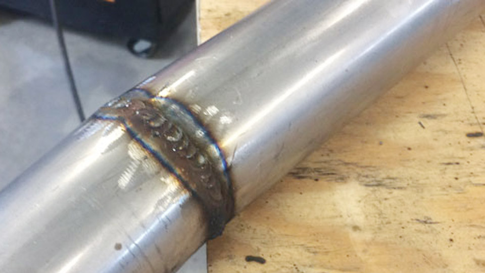
Many beginners fire up a MIG machine outdoors or on farm equipment, only to watch the arc sputter, the bead fill with porosity, or the wire burn back into the tip. The root cause is almost always a solid-wire setup left in place when the job calls for gasless MIG welding for beginners.
Without external shielding gas the process relies on self-shielded flux-cored wire, reversed polarity, longer stick-out, and a drag technique. Getting any one of those wrong produces weak fusion, excessive spatter, or complete arc failure.
Correct parameters deliver portable, wind-tolerant welds on mild steel from roughly 16-gauge to ⅜ inch with equipment most hobbyists already own. The difference between usable results and wasted wire is measured in voltage taps, wire-feed speed, and contact-tip-to-work distance.
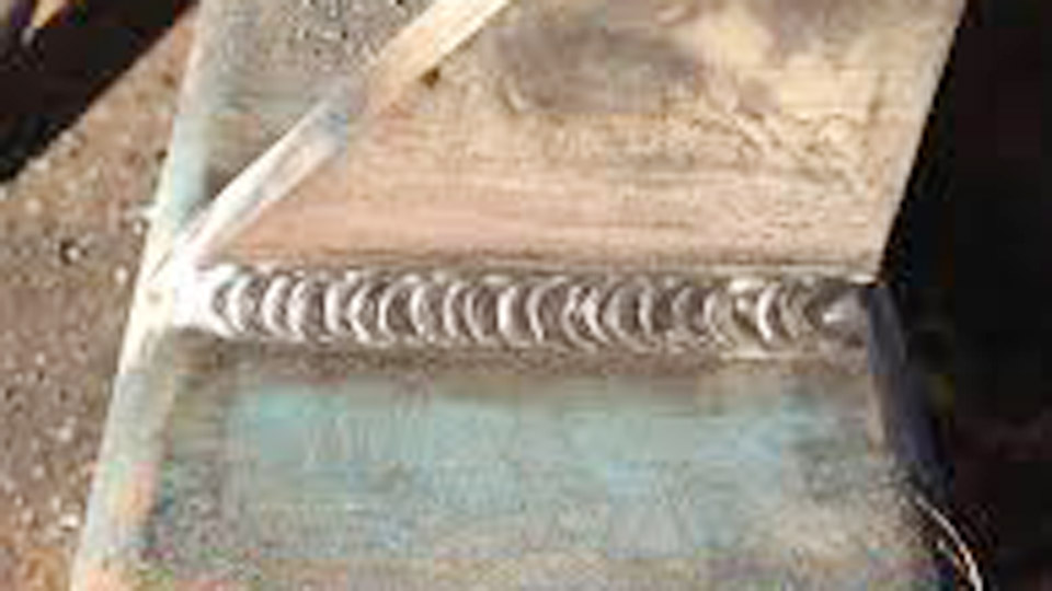
Image by fb/I See You Don’t Know Shit About Welding
Why Polarity Must Change Before the First Arc
Self-shielded flux-cored wires such as E71T-11 and E71T-GS require DC electrode negative (DCEN). Most machines leave the factory set for solid-wire MIG on DC electrode positive (DCEP).
Running the wrong polarity concentrates heat in the wire instead of the workpiece, overheats the flux, and generates heavy spatter with shallow penetration.
How to Confirm and Swap the Leads
Open the side panel. The gun lead must connect to the negative terminal and the work clamp to the positive terminal. Some units use a polarity block or quick-connect plug; others require physically swapping the cables.
After the change, verify with a quick test bead on scrap. An unstable, spitting arc that refuses to dig in is the usual sign the polarity is still reversed.
What Happens When Polarity Stays Wrong
The flux core decomposes too early in the arc column. Resulting defects include porosity tunnels, undercut, and a bead that sits on the surface rather than fusing.
On thin material the wire often burns back into the contact tip within seconds. Correct polarity restores the quiet crackling sound and deeper penetration that flux-core is known for.
Voltage and Wire-Feed Speed Windows That Produce Usable Beads
Voltage sets arc length and bead width. Wire-feed speed (WFS) largely determines amperage and deposition rate. The two must stay matched; changing one without the other produces either stubbing or excessive spatter.
Starting Ranges for Common 0.030-Inch Wire
On clean mild steel in the flat position with ½–¾ inch stick-out:
| Material Thickness | Voltage | Wire Speed (IPM) | Approx. Amps |
|---|---|---|---|
| 16–18 ga | 15–17 V | 150–220 | 70–110 A |
| 1/8 inch | 17–19 V | 220–300 | 100–140 A |
| 3/16–1/4 inch | 19–21 V | 280–360 | 130–170 A |
These values reflect typical E71T-11 performance on 120 V and 240 V machines. Always begin at the middle of the range and adjust one parameter at a time.
Adjustments for 0.035-Inch Wire and Thicker Plate
Step up to 0.035-inch wire once material reaches 3/16 inch or the machine exceeds roughly 180 A output. Expect 18–22 V and 250–380 IPM for 1/4-inch plate, producing 140–200 A. Higher settings increase deposition but also heat input; on restrained joints this can raise the risk of distortion or cracking if interpass temperature is ignored.
Sound and Visual Feedback for Fine-Tuning
A steady frying-bacon crackle indicates balanced parameters. Loud popping and BB-sized spatter usually mean voltage is too low or WFS is too high. A harsh, wide arc with undercut points to excess voltage. Make 5–10 IPM or ½-volt changes and retest; large jumps hide the correct window.
Stick-Out Length and Torch Angle That Keep the Arc Stable
Contact-tip-to-work distance (CTWD or stick-out) directly affects resistance heating of the wire and therefore actual current. Self-shielded flux-core runs longer stick-out than short-circuit solid-wire MIG.
Recommended Stick-Out by Wire Diameter
Most E71T-11 data sheets list ⅜–½ inch for 0.030-inch wire and ½–⅝ inch for 0.035-inch wire. Maintaining a consistent distance is more important than the exact number. Pulling the gun away lengthens the stick-out, lowers current, and can cause porosity; pushing closer raises current and risks tip burn-back.
Work Angle and Travel Angle Decisions
Hold a 10–20 degree drag (pull) angle so the arc points into the puddle. A work angle of 45 degrees works for most fillet joints; reduce it toward 30 degrees on open roots to improve penetration. Excess angle increases spatter and can trap slag at the toes.
Drag Technique Versus Push: When Each Produces Defects
Flux-cored wire generates a slag layer that must form behind the arc. Pushing the gun forces the slag ahead into the molten pool and creates inclusions or worm-hole porosity. Dragging keeps the slag trailing and allows deeper fusion.
Travel Speed Linked to Heat Input
Typical travel speeds fall between 8–14 inches per minute on ⅛-inch plate. Too slow builds excessive reinforcement and raises the chance of slag entrapment; too fast leaves incomplete fusion at the toes. Watch the leading edge of the puddle—keep the arc at the front of the molten pool rather than in the middle.
Multi-Pass Sequencing Limits
Many E71T-11 wires are limited to three passes to maintain mechanical properties and chemistry. On thicker sections, clean each pass thoroughly before the next. Residual slag left between layers becomes a linear defect that fails bend or radiographic tests.
Material Thickness Decisions and When to Change Wire Size
Wire diameter and machine output set the practical upper limit for single-pass work. 0.030-inch wire on a 140 A machine handles up to roughly ¼ inch with multiple passes. Beyond that, 0.035-inch or larger wire on a higher-output unit becomes necessary for acceptable deposition rates.
Thin-Gauge Constraints
Below 16 gauge the process risks burn-through even at the lowest stable settings. Reduce WFS, increase travel speed, and consider intermittent welds or a heat-sink backing bar. Some operators switch to a smaller 0.030-inch wire specifically for sheet-metal repairs.
Outdoor and Contaminated-Surface Performance
Self-shielded flux-core tolerates light rust, mill scale, and moderate wind that would blow away external shielding gas. Heavy paint, oil, or thick scale still require grinding. The flux deoxidizers help, but they cannot compensate for gross contamination that produces porosity or lack of fusion.
Diagnosing Spatter, Porosity, and Lack of Fusion from Settings Alone
Excess spatter that sticks to the nozzle usually traces to incorrect voltage/WFS balance, wrong polarity, or excessive stick-out. Porosity tunnels appear when stick-out is too long, travel speed is too fast, or the flux has absorbed moisture.
Lack of fusion at the root or toes results from insufficient amperage, too fast travel, or an incorrect work angle that fails to direct the arc into the joint.
Contact Tip and Drive-Roll Checks
Flux-cored wire is softer than solid wire. Knurled drive rolls set to moderate tension prevent crushing yet still feed reliably. A worn or mismatched contact tip causes erratic current transfer and bird-nesting inside the gun. Replace tips when the orifice shows egg-shaped wear.
Moisture Control on the Wire Spool
Self-shielded wires absorb atmospheric moisture. Store opened spools in a sealed container or heated cabinet. Damp flux produces hydrogen-induced porosity that no amount of parameter adjustment can eliminate.
Wrapping Up
Choosing gasless MIG for a given job rests on three technical decisions: outdoor or windy conditions favor self-shielded wire; material thicker than ⅛ inch benefits from the higher deposition and penetration; and the absence of a gas cylinder simplifies portability.
When those factors align, correct DCEN polarity, matched voltage and wire speed, and consistent drag technique produce strong, serviceable welds on mild steel.
Advanced operators further refine heat input by combining short stringer beads with controlled interpass temperatures rather than wide weaves, preserving toughness on restrained structural joints.
FAQs
Does gasless MIG welding require a polarity change?
Yes. Most self-shielded flux-cored wires run on DCEN. Leaving the machine on DCEP produces excessive spatter and poor penetration.
What wire size should beginners start with for gasless MIG?
0.030-inch E71T-11 or E71T-GS covers the majority of light fabrication and repair work up to ¼ inch on typical 120–180 A machines.
Can gasless MIG weld through rust or paint?
Light surface rust and mill scale are tolerable because of the flux deoxidizers. Heavy scale, thick paint, or oil still require cleaning for reliable fusion.
How much stick-out is correct for flux-core wire?
Maintain ½–¾ inch for most 0.030- and 0.035-inch self-shielded wires. Consistent distance matters more than the precise number.