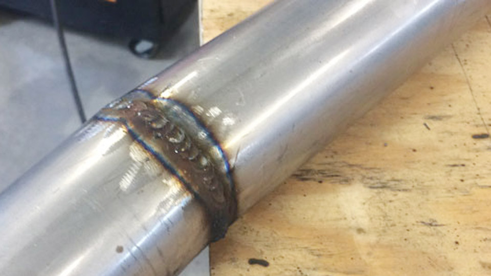
Excessive spatter turns a clean MIG bead into a cleanup job that costs time and risks coating adhesion problems later. When molten droplets fly from the arc and stick to the plate, nozzle, and fixtures, the process is telling you the metal transfer is unstable.
Learning how to avoid spatter in MIG welding starts with matching voltage to wire feed speed, choosing the right shielding gas, controlling stick-out, and keeping the base metal clean.
These adjustments stabilize short-circuit or spray transfer so droplets enter the puddle instead of exploding outward. The difference shows up immediately in arc sound, bead profile, and the amount of grinding required after the weld.
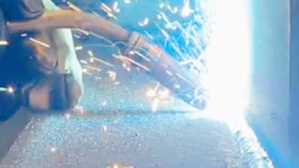
Image by yeswelder
Why Voltage and Wire Feed Speed Create Most Spatter
The single largest source of MIG spatter is a mismatch between voltage and wire feed speed. In short-circuit transfer the wire contacts the puddle dozens of times per second. When feed speed is too high for the set voltage, the wire punches into the pool and the short circuit clears explosively, ejecting metal.
When voltage is too high relative to feed speed the arc lengthens, the droplet grows large, and the transfer becomes erratic.
Matching the Arc Sound to the Correct Balance
A correctly tuned short-circuit arc produces a steady frying-bacon crackle. Loud popping and large cold droplets mean voltage is low or wire speed is high—raise voltage 0.5–1 V or drop wire speed 5–10 %.
A high-pitched hiss with fine spray and undercut means voltage is high—lower it slightly. Change only one variable at a time and test on scrap of the same thickness.
Typical Starting Ranges for 0.030–0.035 in ER70S-6
On 1/8 in mild steel with C25 gas, start near 18–20 V and 220–280 ipm. On 1/4 in plate move toward 20–22 V and 280–350 ipm. These windows keep the process in true short-circuit transfer and away from the high-spatter globular transition zone that appears between roughly 22–26 V on common argon-CO₂ mixes.
Choosing Shielding Gas That Stabilizes Metal Transfer
Shielding gas composition directly controls arc stiffness and droplet detachment. Pure CO₂ produces deeper penetration but a harsher, more reactive arc that throws more spatter. Argon-rich blends soften the arc and promote smoother transfer.
Comparing Common Gas Mixes for Spatter Control
| Gas Mix | Spatter Level | Penetration | Typical Use |
|---|---|---|---|
| 100 % CO₂ | High | Deep | Thick structural, cost focus |
| 75 % Ar / 25 % CO₂ | Low–moderate | Balanced | General mild steel |
| 85–90 % Ar / 10–15 % CO₂ | Low | Slightly less | Cosmetic or thin material |
| 95–98 % Ar / 2–5 % CO₂ | Very low | Controlled | Spray transfer or stainless |
Setting Flow Rate Without Creating Turbulence
Run 20–25 CFH for most indoor short-circuit work. Below 15–18 CFH the shield collapses and atmospheric contamination destabilizes the arc. Above 30–35 CFH the high velocity creates turbulence that pulls air into the gas stream, producing the same porosity and spatter symptoms. Confirm actual flow at the nozzle rather than relying only on the regulator reading.
Controlling Stick-Out and Gun Angle for Arc Stability
Contact-tip-to-work distance (stick-out) acts as a resistor in the welding circuit. Excess length preheats the wire, lowers effective current, and makes droplet detachment irregular. Gun angle that is too steep pushes the gas shield to one side and creates a Venturi effect that draws air into the arc.
Maintaining Consistent Stick-Out
For solid-wire short-circuit MIG keep stick-out between ⅜ and ½ in (10–13 mm). That distance is roughly the width of a fingertip. Longer stick-out increases resistance heating and spatter; shorter stick-out can cause burn-back into the tip. Measure from the end of the contact tip, not the nozzle face.
Selecting Travel and Work Angles
A 5–15° push or slight drag angle keeps the gas envelope centered over the puddle. Angles steeper than 20° often produce one-sided spatter and incomplete shielding. Keep the wire centered in the joint rather than biased to one sidewall; off-center wire creates uneven force that throws metal to the opposite side.
Preparing Base Metal and Consumables Before the Arc Starts
Surface contamination and worn front-end parts introduce arc instability that no parameter change can fully overcome. Mill scale, rust, oil, paint, and coatings vaporize in the arc and disrupt metal transfer. A worn or oversized contact tip lets the wire wander, changing electrical contact point continuously.
Cleaning Requirements That Directly Cut Spatter
Grind the weld zone to bright metal with a flap disc and extend the clean area at least ½ in beyond the joint edges. Solvent wipe after grinding if residual oils remain. ER70S-6 tolerates light contamination better than many wires, but heavy scale still forces higher voltage and more spatter to achieve fusion.
Contact Tip, Nozzle, and Liner Condition
Replace the contact tip when the bore becomes oval or when the wire begins to feed inconsistently. Match tip size exactly to wire diameter—oversized tips allow lateral movement that destabilizes the arc. Clean the nozzle and gas diffuser of accumulated spatter; a restricted gas path produces the same turbulence as excessive flow rate.
Check drive-roll tension and liner condition so wire feed remains constant; intermittent feeding creates the same explosive shorts as excessive wire speed.
Using Inductance and Transfer Mode to Soften the Arc
Many inverter machines include an inductance or arc-control knob that governs how fast current rises during the short-circuit phase. Low inductance produces a sharp, explosive clear of the short and high spatter. Higher inductance slows the current rise, giving the puddle more time to wet and absorb the droplet.
Adjusting Inductance on Short-Circuit Settings
Increase inductance gradually until the arc softens and the popping diminishes without the puddle becoming sluggish. The ideal setting varies with wire diameter, gas mix, and machine design; test on scrap rather than accepting the factory default.
On machines without a dedicated control, the same effect is sometimes achieved by slight voltage increases within the stable window.
Moving Out of the Globular Transition Zone
Globular transfer occurs in the intermediate voltage/current band and produces large, irregular droplets with the highest spatter of any conventional MIG mode. Either stay in true short-circuit (lower voltage and wire speed) or move fully into spray transfer (higher voltage, higher current, higher-argon gas).
Pulsed MIG electronically crosses the transition and can deliver near-zero spatter while retaining control on thinner material.
Diagnosing Spatter Patterns to Isolate the Root Cause
Different spatter signatures point to different root causes and allow faster correction.
Reading Spatter Size, Location, and Arc Behavior
Large, cold, round droplets usually indicate low voltage or excessive wire speed. Fine, hot spray with undercut points to high voltage. Spatter concentrated on one side of the bead often traces to gun angle or magnetic arc blow.
Spatter accompanied by porosity almost always involves gas coverage, drafts, or surface contamination. Stubbing with heavy build-up on the tip signals either low voltage or excessive stick-out.
Systematic Correction Sequence
Clean the metal and verify polarity (DCEP for solid wire). Confirm gas mix and flow at the nozzle. Inspect and replace the contact tip if worn. Set stick-out to ⅜–½ in.
Start from the manufacturer chart for wire diameter and thickness, then adjust voltage or wire speed in small increments while listening to the arc. Only after the arc stabilizes should technique variables such as travel speed be refined.
Wrapping Up
When voltage, wire feed, gas, stick-out, and surface condition are brought into the correct window, spatter drops dramatically and the arc settles into a consistent frying-bacon sound. The remaining cleanup is minimal, and the weld is ready for coating or further fabrication without excessive grinding.
Advanced operators further reduce residual spatter by documenting the exact voltage–wire-speed pairs that work on each machine and joint type, then locking those values into a simple process sheet so every operator starts inside the low-spatter window rather than hunting for it on every job.
FAQs
Why does my MIG welder produce so much spatter?
The most common cause is voltage too low or wire feed speed too high for the selected voltage, producing violent short-circuit clearing. Clean the metal, set stick-out to ⅜–½ in, switch to C25 gas if using pure CO₂, and raise voltage or lower wire speed in small steps until the arc sounds like steady frying bacon.
What gas reduces MIG spatter the most on mild steel?
A 75 % argon / 25 % CO₂ (C25) mix gives the best balance of low spatter and usable penetration for short-circuit MIG. Higher-argon blends (85–95 % Ar) reduce spatter further but cost more and slightly reduce penetration.
How long should stick-out be to avoid spatter?
Keep contact-tip-to-work distance between ⅜ and ½ in (10–13 mm) for solid-wire short-circuit MIG. Longer stick-out increases wire resistance, lowers effective current, and makes droplet transfer erratic.
Does inductance setting affect MIG spatter?
Yes. Higher inductance slows current rise during the short circuit, softens the arc, and reduces the explosive ejection of metal. Increase the inductance or arc-control setting gradually on inverter machines until the popping diminishes without the puddle becoming too fluid.