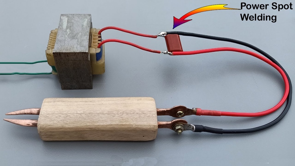
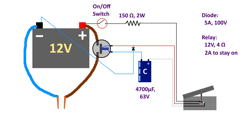
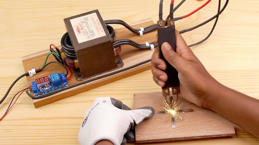
A spot weld can look clean and properly formed without having enough strength to withstand the loads placed on the joint. Knowing how to check spot welding strength is essential for identifying weak welds, incomplete fusion, inconsistent nugget formation, and other defects that can lead to joint failure.
In automotive bodywork, sheet metal fabrication, and industrial manufacturing, weld quality directly affects joint reliability, product safety, and repair costs. Visual inspection can reveal surface defects, but it cannot always confirm the strength of the weld itself.
Depending on the application, methods such as destructive peel testing, chisel testing, and specialized mechanical testing may be needed to evaluate weld performance.
Understanding which inspection method to use, what signs of a strong weld to look for, and how to recognize common failure patterns helps you assess weld quality more accurately and determine whether a joint meets the required specifications.
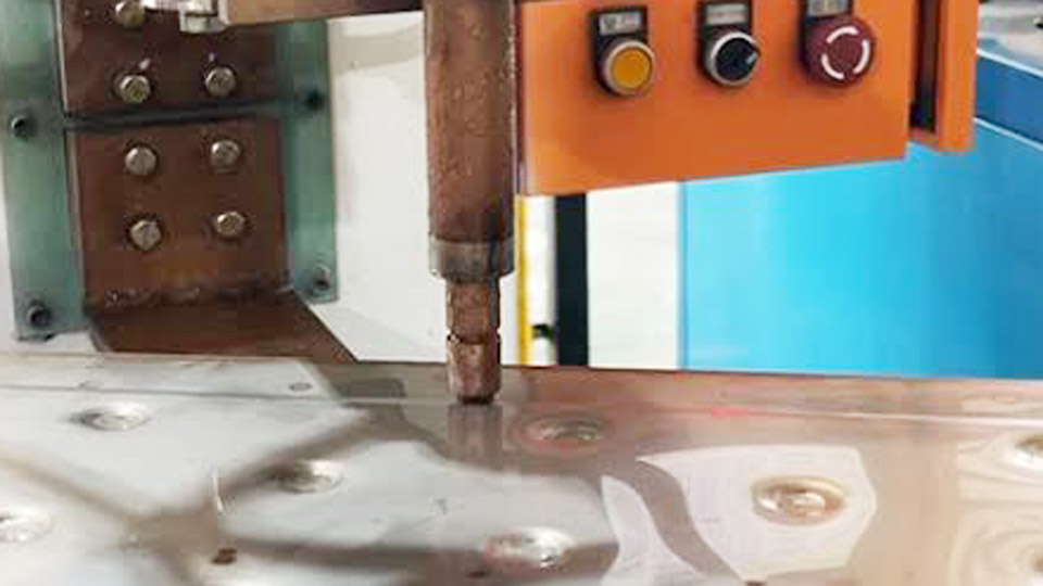
Image by resistance-welding
Destructive Tests That Directly Confirm Nugget Integrity
Destructive methods remain the reference standard because they expose the actual fused zone and the failure path under load. They are used for procedure qualification, electrode setup, and periodic process validation.
Peel Test Execution and Acceptance Criteria
Clamp one sheet in a vise or use pliers to peel the second sheet away from the weld. Force is applied progressively until separation occurs. A successful result produces a full button or plug pull-out: the nugget tears out of one sheet, leaving a hole, while the parent metal around the weld fails rather than the weld itself.
Measure the button diameter in two perpendicular directions and average the values. Acceptance requires the average diameter to meet or exceed the specified minimum for the governing metal thickness.
Partial buttons, interfacial fractures through the original faying surface, or no visible nugget indicate insufficient heat input or electrode force.
Chisel Test for Rapid Shop-Floor Checks
Drive a tapered chisel between the sheets immediately adjacent to the weld until the joint separates. The chisel edges must not contact the weld nugget itself. The same acceptance rules apply as the peel test: full button pull-out of adequate diameter is required.
This method suits multi-spot assemblies or thicker gauges where full peeling is impractical. Automated hydraulic versions improve consistency on production lines. Results correlate reasonably with tensile-shear strength when button diameters exceed approximately (t in mm) on mild steel.
Tensile Shear Testing for Quantified Load Values
Prepare overlapping coupons with a single spot weld centered in the overlap. Mount the specimen in a universal testing machine and pull parallel to the sheets at a controlled rate until failure. Record the peak force (tensile shear strength). ISO 14273 and related standards define specimen dimensions for thicknesses from 0.5 mm to 10 mm.
For low-carbon steel of 280 N/mm² minimum tensile strength, typical minimum shear strengths rise with both thickness and nugget size. Example values at a nominal nugget include roughly 4.3 kN for 1.0 mm sheet and 10.8 kN for 2.0 mm sheet. Failure mode is also recorded: pull-out is preferred over pure interfacial shear for ductile performance.
Interpreting Failure Modes and Minimum Nugget Requirements
The fracture appearance after testing supplies more information than a single load number. Designers and inspectors use both geometry and mode to accept or reject a weld schedule.
Button Pull-Out Versus Interfacial Failure
Button (or plug) pull-out occurs when the weld is stronger than the surrounding heat-affected zone or base metal; the sheet tears around the nugget. Interfacial failure splits the original faying surface through the center of the nugget and usually indicates undersized fusion, insufficient current, or contamination.
Partial interfacial fractures combine both modes and are treated as borderline. On higher-strength steels the preference for full pull-out becomes stricter because interfacial failure can produce lower energy absorption under dynamic loading.
Minimum Nugget Size Rules by Sheet Thickness
Industry practice and standards such as ISO 14373 and automotive guidelines commonly set the minimum nugget diameter between and or , where t is the thickness of the thinner sheet in millimeters. For 0.8 mm sheet a (5\sqrt{t}) target is approximately 4.5 mm; for 1.5 mm sheet it rises to about 6.1 mm.
Larger diameters increase absolute strength but reduce average unit stress because failure shifts toward the periphery. Always verify against the governing metal thickness in multi-sheet stack-ups and against any customer drawing note that overrides the generic formula.
Non-Destructive Options When Parts Cannot Be Destroyed
Production parts or finished assemblies require methods that leave the weld intact while still providing usable quality data.
Ultrasonic Inspection for Nugget Size and Internal Defects
A focused high-frequency transducer (typically 15–20 MHz for thin sheet) is coupled to the weld surface. Sound attenuation and echo patterns reveal whether a proper nugget formed. A good weld shows rapid amplitude decay and echo intervals matching the combined sheet thickness.
Stick welds or cold bonds produce longer echo trains from the individual sheets; incomplete fusion yields short intervals corresponding only to the upper sheet.
Modern systems can estimate diameter and detect porosity or cracks with accuracy approaching 95 % of destructive results when calibrated on the same material. Portable units allow sampling on the line; automated probes integrated into weld guns enable 100 % monitoring in high-volume plants.
Visual and Indentation Assessment Limits
Surface examination checks for excessive expulsion, deep electrode indentation, cracks, or irregular shape. Indentation depth is typically limited to 20–30 % of sheet thickness to avoid stress concentrations. Visual checks alone cannot confirm internal fusion diameter or strength; they serve only as a first filter before quantitative testing. Expulsion marks may indicate over-current but do not guarantee an undersized nugget.
Selecting the Appropriate Test Method for the Application
Method choice depends on required data type, available equipment, part value, and risk level of the joint.
Shop-Floor Versus Laboratory Requirements
Peel and chisel tests need only hand tools or a simple fixture and deliver immediate go/no-go decisions on button size. They suit electrode dressing checks, shift start-up, and high-volume sampling.
Tensile-shear and cross-tension tests require a calibrated load frame and standardized coupons; they supply absolute force values needed for design validation and material qualification.
Ultrasonic testing bridges the gap when parts cannot be sacrificed, provided the operator is trained on the specific thickness and coating combination.
Matching Test Frequency to Process Risk
Critical structural joints or new material combinations demand higher sampling rates and quantitative strength data until the process capability is proven. Routine production on well-characterized mild steel can rely on periodic peel or ultrasonic checks once the lobe curve is established.
Any change in electrode face diameter, cooling, or surface condition triggers immediate re-verification. Record both the measured diameter or load and the failure mode so trends in electrode wear or current drift become visible before rejects appear.
Practical Decision Criteria for Acceptance
Acceptance rests on two linked requirements: the measured nugget or button diameter must meet the minimum size for the governing thickness, and the failure mode under destructive testing must be predominantly pull-out rather than interfacial.
When only non-destructive data are available, ultrasonic signals must match the calibrated signature of a known good weld of that diameter.
Strength values from tensile-shear testing are compared against tabulated minima or drawing-specified allowables. Any interfacial failure on steels above roughly 420 MPa yield strength usually triggers schedule adjustment even if the diameter appears marginal.
Consistent electrode force, clean surfaces, and verified current delivery remain the upstream controls that make downstream tests pass.
Final Talk
The choice between a quick peel check and a full tensile-shear series is driven by the consequences of an undersized nugget and by the need for absolute load data versus geometric confirmation. Once the schedule is locked, ultrasonic sampling maintains confidence without destroying every part.
Advanced process control closes the loop by feeding real-time ultrasonic or dynamic-resistance signatures back into adaptive current adjustment, converting periodic strength verification into continuous quality assurance.