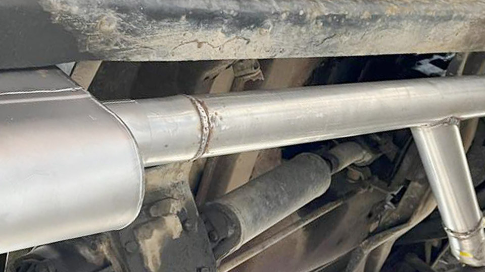
Conventional fusion processes struggle with aluminum’s oxide layer, high thermal conductivity, and susceptibility to hot cracking or distortion. Resistance spot welding degrades electrodes rapidly on aluminum, while laser methods demand precise surface preparation and still risk porosity.
Ultrasonic welding aluminum solves these issues by creating a solid-state bond through high-frequency vibration and clamping force, generating localized friction that disperses oxides and forges metal-to-metal contact without melting.
The process delivers short cycle times, minimal heat input, and reliable electrical conductivity—critical for battery tabs, busbars, foil packages, and thin structural sheet.
Selecting the correct amplitude, force, and time determines whether the joint achieves full interfacial bonding or suffers under-weld, excessive indentation, or sonotrode wear.
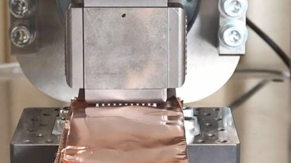
Image by avioweld
Core Process Parameters That Control Bond Formation
Amplitude, clamping force, and weld time interact to determine interfacial temperature, plastic flow, and final shear strength. Frequency is usually fixed by the machine (most commonly 20 kHz for metal welding).
Amplitude Range and Its Effect on Oxide Disruption
Peak-to-peak amplitude at the sonotrode tip typically falls between 25 µm and 60 µm for aluminum. Lower amplitudes (25–35 µm) suit thin foils and delicate tabs; higher values (40–55 µm) improve bonding on thicker or harder alloys by increasing relative motion and frictional heat.
Excess amplitude accelerates sonotrode wear and can produce excessive thinning or surface marking. Studies on AA6061-T6 and pure aluminum show that raising amplitude toward the upper end of the machine’s capability consistently increases tensile-shear failure load until a plateau is reached, after which further increases mainly deepen knurl penetration.
Clamping Force Requirements for Different Sheet Thicknesses
Force must be high enough to maintain intimate contact and break residual oxides yet low enough to avoid crushing thin material. Typical values range from 800 N to 4000 N (roughly 1.5–7 bar system pressure depending on tip area). For 0.3–1.0 mm aluminum-to-aluminum joints, 1500–3000 N is common.
Higher force increases interfacial temperature and bond area up to an optimum; beyond that point the material extrudes sideways, reducing effective joint thickness and strength. Rigid fixturing is essential—any compliance in the anvil or part support dissipates vibration energy and produces inconsistent results.
Weld Time and Energy Modes for Consistent Results
Most aluminum ultrasonic welds complete in 0.15–0.6 s. Time mode remains the dominant control strategy for metals because power and collapse distance can vary with surface condition. Energy mode (targeting a fixed joule value) improves consistency when part thickness or surface oxide varies slightly.
Holding time after vibration ceases (typically 0.2–0.5 s) allows the forged interface to cool under pressure and prevents spring-back separation. Over-long weld times generate excessive heat, promoting dynamic recrystallization that softens the heat-affected zone and can initiate micro-cracks at the knurl tips.
Thickness Limits and Joint Configuration Decisions
Aluminum’s low acoustic impedance and high thermal conductivity restrict reliable ultrasonic welding to thinner sections than steel or copper.
Practical Thickness Windows for Aluminum Sheet
Single-sheet thickness is generally limited to approximately 3 mm; most production applications stay below 2.5 mm. Foils and battery tabs (0.1–0.5 mm) weld readily at moderate power.
Multi-layer stacks of thin aluminum (three or more 0.2–0.3 mm sheets) are common in electrical interconnects and remain within process capability provided total stack height stays under the machine’s design limit.
When one sheet exceeds 2 mm, energy transmission to the far interface declines sharply, requiring higher power systems or dual-sonotrode configurations.
Lap Joint Geometry and Knurl Pattern Influence
Overlaps of 10–25 mm are typical. Sonotrode tip geometry—knurl density, tooth height, and contact area—directly affects bonding area and indentation depth. Finer knurls reduce surface marking on cosmetic parts but may require longer time or higher amplitude to achieve equivalent strength.
Coarser patterns improve grip on thicker sheet yet increase the risk of local thinning. Anvil design must match the sonotrode pattern so that both sides of the joint experience controlled plastic deformation.
Microstructural Changes and Mechanical Performance
The solid-state nature of the process produces distinctive interfacial features that govern strength and conductivity.
Interfacial Bonding Mechanisms Without Melting
High-frequency shear breaks the continuous oxide film into discontinuous particles that are dispersed into the surrounding matrix. Fresh metal surfaces then form metallurgical bonds through atomic diffusion and mechanical interlocking under the combined action of pressure and localized heating (typically reaching 0.3–0.5 of absolute melting temperature).
Dynamic recrystallization occurs in a narrow zone adjacent to the interface, refining grain size and often producing a slight hardness drop relative to the parent metal. No bulk melting or solidification cracking occurs.
Achievable Shear Strength and Failure Modes
Optimized AA6061-T6 spot joints have demonstrated tensile-shear failure loads above 5 kN under laboratory conditions. Pure aluminum and softer alloys frequently fail in the base metal outside the weld zone once full bonding is achieved. Under-welded joints separate at the interface with low load and limited bonded area.
Over-welded joints show excessive indentation, reduced effective thickness, and occasional edge cracks that lower fatigue life. Electrical resistance of a properly formed aluminum ultrasonic joint remains very low, making the process suitable for high-current applications.
Equipment and Tooling Considerations Specific to Aluminum
Machine selection and tool maintenance directly affect process stability.
Frequency and Power Matching
20 kHz systems dominate metal welding because they deliver higher amplitude and greater energy delivery for thicker sections. 30–40 kHz systems offer quieter operation and finer control for micro-scale tabs or foil but limit maximum thickness.
Power ratings of 1–4 kW cover most aluminum applications; higher-power units extend capability toward the upper thickness limit. Amplitude profiling—starting high to break oxides then reducing to limit indentation—has been shown to increase joint strength while reducing surface marking on aluminum.
Sonotrode and Anvil Material Selection
Titanium or hardened tool-steel sonotrodes with wear-resistant coatings are preferred. Aluminum’s abrasive oxide particles accelerate tip wear; regular inspection of knurl condition is required. Anvil surfaces must remain flat and properly patterned. Any loss of knurl definition reduces grip and increases the chance of interfacial slip without bonding.
Process Monitoring and Quality Control Decisions
Real-time feedback prevents both under- and over-welding in production.
Power, Collapse, and Time Signatures
Modern controllers record peak power, energy delivered, and collapse distance (thickness reduction under the tip). A stable power curve that rises quickly then plateaus indicates good bonding. Sudden power spikes or excessive collapse signal over-welding or part misalignment.
Setting upper and lower limits on these signals enables automatic rejection of suspect joints without destructive testing of every part.
Surface Condition Tolerance
Unlike fusion processes, ultrasonic welding tolerates light residual oils or thin oxide layers because the vibration itself performs mechanical cleaning. Heavy grease, thick anodizing, or heavy mill scale still require removal. Pre-cleaned or degreased surfaces produce the most consistent results and lowest energy demand.
Wrapping Up
Selecting the correct combination of amplitude, force, and time for a given aluminum thickness and alloy determines whether the joint reaches full interfacial strength or remains limited by incomplete oxide disruption or excessive thinning.
Production systems that combine time or energy control with power and collapse monitoring deliver the highest process capability for battery interconnects, electrical busbars, and thin structural assemblies.
Advanced practitioners further refine performance by applying amplitude profiling and dual-sonotrode configurations on multi-layer stacks, reducing energy input while maintaining or increasing joint strength beyond single-amplitude baselines.
Faqs
What frequency is used for ultrasonic welding aluminum?
Most industrial metal systems operate at 20 kHz. Higher frequencies (30–40 kHz) are used for thinner foils or micro-scale joints where lower amplitude and reduced noise are preferred.
What is the maximum thickness for ultrasonic welding aluminum?
Reliable single-sheet welding is generally limited to about 3 mm; most production work stays below 2.5 mm. Multi-layer thin sheets can be stacked provided total thickness remains within machine capability.
Can ultrasonic welding join aluminum to copper?
Yes. The solid-state process is widely used for Al–Cu battery tabs and busbars. Careful parameter control limits intermetallic growth while still achieving low electrical resistance and adequate mechanical strength.
How long does an ultrasonic weld on aluminum take?
Typical weld times range from 0.15 s to 0.6 s. Thinner foils complete faster; thicker or multi-layer stacks may require the upper end of this range or energy-mode control.