The wire suddenly fuses inside the contact tip, the arc cuts out with a sharp pop, and welding stops mid-bead. That is burn back in MIG welding, and it is one of the most frequent interruptions on both shop floors and home benches.
When the electrode melts faster than the feeder can deliver it—or when delivery slows for even a fraction of a second—the arc climbs back into the tip and welds the wire in place. The result is ruined consumables, lost arc time, and inconsistent starts that compromise joint quality.
Understanding the precise mechanical and electrical conditions that create this imbalance is the only reliable way to eliminate it rather than simply replacing tips after every occurrence.
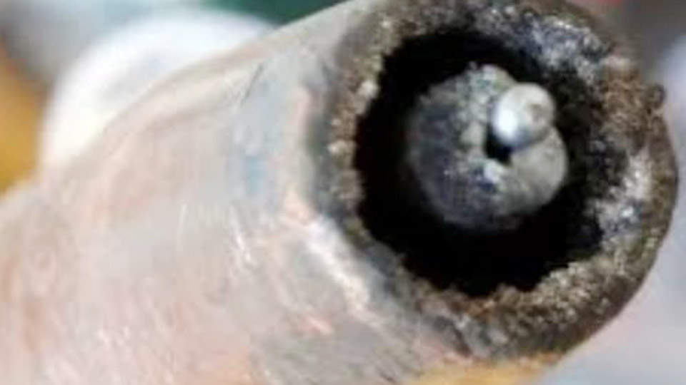
Image by yeswelder
Wire Feed Speed Versus Arc Melting Rate
Burn back occurs when the rate at which the arc consumes wire exceeds the rate at which the feeder supplies it. The mismatch is usually parameter-driven rather than a pure mechanical failure.
Low Wire Feed Speed Relative to Voltage
If voltage is set for a fluid short-circuit or spray arc while wire-feed speed sits too low, the arc lengthens and melts the free end of the wire before fresh electrode arrives. Typical symptom: the arc starts cleanly for a second or two, then the tip suddenly plugs.
Increasing wire-feed speed in small increments (5–10 ipm) while holding voltage constant often restores balance. The correct relationship keeps the electrode end just ahead of the melting front so the arc remains at the workpiece rather than climbing the wire.
Voltage Too High for the Chosen Wire Speed
Excess voltage increases arc energy and melting rate without a corresponding increase in electrode delivery. The free wire length shortens rapidly until the molten end reaches the contact tip bore. Lowering voltage slightly or raising wire speed restores the equilibrium.
Many operators reverse the order and chase voltage first; the more efficient sequence is to verify mechanical feed first, then adjust the speed-voltage pair.
Intermittent Feed Hesitation Under Load
Even when average wire-feed speed is correct, brief pauses caused by binding allow the arc to consume the exposed wire. The hesitation may last only a fraction of a second, yet that is enough for the molten ball to fuse inside the tip. These micro-pauses are almost always mechanical and must be eliminated before further parameter changes.
Contact Tip Size, Wear, and Electrical Contact
The contact tip is the final current-transfer point and the narrowest restriction in the wire path. Any deviation from smooth, low-resistance passage concentrates heat and friction exactly where burn back becomes visible.
Wrong Tip Bore Diameter
An undersized tip creates continuous drag that slows the wire under the heat of the arc. An oversized or worn tip reduces electrical contact area, produces micro-arcing inside the bore, and allows the wire to wander.
Both conditions raise local temperature until the wire softens and fuses. Match the tip marking exactly to the wire diameter and to the gun’s consumable series; generic or mixed tips frequently introduce the problem.
Spatter Buildup and Bore Distortion
Spatter that packs inside the tip or on the diffuser face traps heat and constricts the wire path. Once the bore becomes oval or pitted, electrical transfer becomes intermittent.
The tip then overheats rapidly, discoloration appears (blue or purple), and burn back follows within a few starts. Replacement is required; cleaning an already distorted bore rarely restores reliable performance.
Loose Tip Seating
A tip that is not fully seated or is cross-threaded increases resistance at the thread interface. Current transfer becomes inefficient, heat builds at the diffuser-tip junction, and the wire melts back under the elevated temperature.
Always seat the tip firmly with the correct wrench; overtightening that strips soft copper threads creates the same resistance problem on subsequent installations.
Stickout Distance and Heat Proximity
Contact-tip-to-work distance (stickout) controls both electrical resistance and the thermal load on the tip itself.
Excessively Short Stickout
Holding the tip too close to the puddle places the copper tip inside the high-temperature zone of the arc and molten pool. Heat soaks into the tip faster than the shielding gas and mass of the gun can remove it. The elevated tip temperature softens the incoming wire, increasing the probability of fusion.
Maintain a consistent stickout appropriate to the transfer mode—typically longer for higher-current spray or pulsed processes, shorter but still controlled for short-circuit transfer.
Inconsistent Stickout During Travel
Varying the distance while welding produces continuous changes in arc length and resistance. Moments of reduced stickout raise tip temperature and momentarily increase melting rate relative to feed speed.
The result is intermittent burn back that appears random until the operator’s hand position is examined. A fixed gun angle and steady standoff eliminate this variable.
Tip Recess Relative to Nozzle
The tip should sit slightly recessed inside the nozzle for most short-circuit applications so that the nozzle can protect the tip from direct spatter and heat. A protruding tip absorbs more radiant and conductive heat and is more susceptible to burn back. As amperage rises, greater recess is generally beneficial.
Mechanical Restrictions in the Wire Path
Any point of increased friction between the drive rolls and the contact tip can cause the wire to pause while the arc continues to melt it.
Liner Condition and Cable Routing
A dirty, kinked, or incorrectly trimmed liner raises drag. Metal shavings from oversized drive-roll pressure accumulate inside the liner and create progressive restriction. Sharp bends in the gun cable amplify the friction. The diagnostic test is simple: remove the contact tip and jog the wire.
Smooth, consistent delivery with the tip removed and rough or hesitant delivery with the tip installed points first to the tip; continued roughness with the tip removed points upstream to the liner or drive system. Replace the liner when drag persists after cleaning, and keep the gun lead as straight as practical during welding.
Drive-Roll Pressure and Groove Selection
Insufficient pressure allows the rolls to slip under the load of a restricted tip or liner; the motor continues to turn while the wire stops. Excessive pressure flattens solid wire or shaves soft wire, packing debris into the liner and creating new restriction.
Use the correct groove type and size for the wire (V-groove for solid steel, knurled for flux-cored). Set tension only high enough to feed without crushing; the wire should not show flat spots after passing the rolls.
Spool Brake and Hub Drag
A brake set too tightly forces the feeder motor to pull against constant resistance. Under arc load the effective wire speed drops and burn back occurs. Adjust the hub so the spool stops promptly when feeding ceases but does not require noticeable motor effort to overcome during feeding.
Electrical Return Path and Arc Stability
Unstable current flow can produce the same net effect as a feed interruption.
Poor Work-Clamp Connection
A loose, painted, or rusty work connection introduces resistance in the return path. Voltage at the arc becomes erratic, starts become violent, and the melting rate fluctuates. The wire may fuse to the tip on the first or second attempt to establish the arc. Clean bright metal under the clamp and locate the clamp as close to the weld zone as practical.
Loose Gun or Power Connections
Any high-resistance joint in the gun power pin, cable lugs, or diffuser threads generates heat and voltage drop. The arc energy available at the tip becomes inconsistent, favoring burn back during the unstable periods.
Periodic inspection and tightening of these joints prevents the problem from appearing as a mysterious consumable failure.
Distinguishing Machine Burnback Control from Unwanted Burn Back
Many modern MIG power sources include an adjustable burnback or “crater-fill” timer. This intentional feature keeps the arc energized briefly after the wire feed stops so the electrode burns free of the puddle and does not freeze in the crater.
When the timer is set too long, the wire continues to melt after feed has ceased and the free end can fuse inside the tip.
Reduce the burnback time in small steps until the wire stops cleanly ¼–½ inch beyond the tip face at the end of each weld. Unwanted burn back during continuous welding is a different phenomenon and is almost never solved by changing the timer alone.
Diagnostic Sequence That Isolates the Cause
Replace the contact tip first with a correctly sized, clean tip and verify that it is tightly seated. Straighten the gun lead and jog wire with the tip removed; note whether feed is smooth. Reinstall the tip and test feed again. If delivery is now consistent, the previous tip was the restriction.
If feed remains hesitant, inspect drive-roll tension, spool brake, and liner. Only after the mechanical path is verified should wire-feed speed and voltage be adjusted. Changing multiple variables at once obscures the true cause and often creates new problems.
Burn back is a balance failure between electrode delivery rate and arc melting rate. When the mechanical path delivers wire at a steady, correct speed, the electrical parameters keep the melting front at the workpiece, and stickout keeps tip temperature under control, the problem disappears.
The advanced operator treats every burn-back event as diagnostic data: the location of the fusion, the timing relative to the trigger, and the condition of the tip together identify whether the fault is parameter, consumable, or feed-path related, allowing a permanent correction rather than repeated tip replacement.
FAQs
Why does my MIG wire keep sticking in the contact tip?
Most often the wire feed speed is too low for the voltage, the stickout is too short, or the tip is worn or the wrong size. Replace the tip, confirm smooth feed, then raise wire speed slightly.
Can a dirty liner cause burn back?
Yes. Liner drag creates brief pauses in wire delivery while the arc continues to melt the electrode, allowing the wire to fuse inside the tip. Clean or replace the liner and keep the gun cable free of tight bends.
What stickout should I use to prevent burn back?
Maintain a consistent contact-tip-to-work distance appropriate to the process—typically enough to keep the tip out of the intense heat of the puddle while still providing stable arc control. Short stickout is a frequent contributor to tip overheating and burn back.
Does increasing drive-roll tension stop burn back?
Only if the rolls were actually slipping. Over-tightening deforms the wire, packs debris into the liner, and often makes burn back worse. Correct the downstream restriction first, then set tension only high enough for reliable feed.