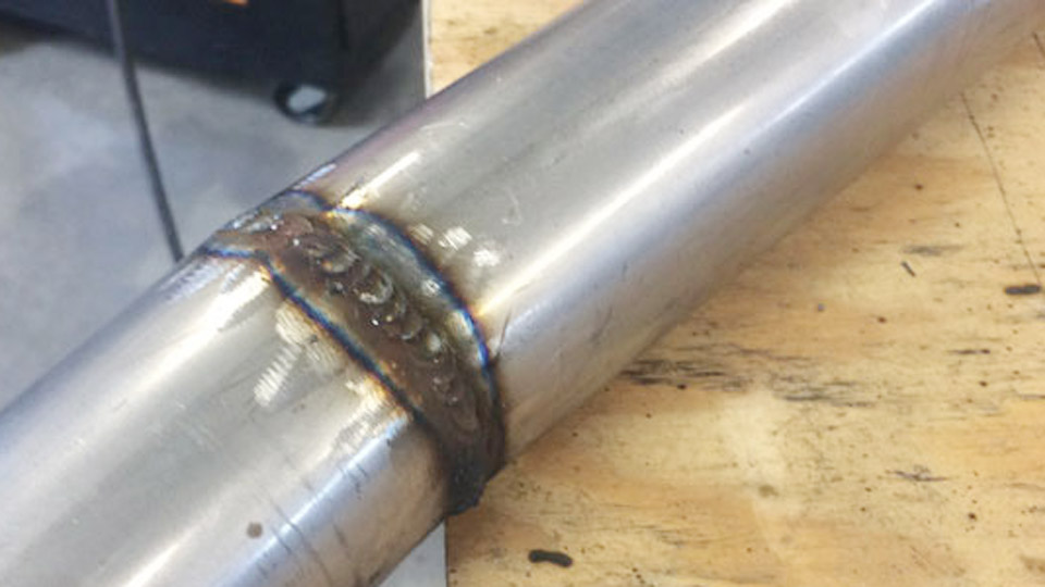
Setting the wrong wire feed speed or voltage on aluminum MIG produces immediate problems: the soft wire bird-nests in the liner, the arc digs and burns through thin sheet, or the puddle stays cold and porous on thicker plate.
An accurate Aluminum MIG Welding Wire Speed and Voltage Chart gives measurable starting points that match ER4043 or ER5356 wire diameter, base-metal thickness, and pure-argon shielding so the process stays in spray or pulsed-spray transfer.
Correct parameters control heat input on a metal that conducts heat four times faster than steel, determine fusion without excessive distortion, and keep the soft filler feeding reliably through a spool gun or push-pull system.
Outside the proven ranges the oxide layer remains unbroken, porosity forms, or the bead collapses. Dialing voltage and wire speed first makes every later decision—travel speed, gun angle, and cleaning—predictable.
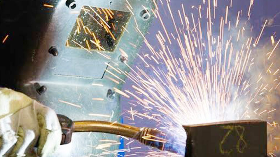
Image by weldingtipsandtricks
Primary Aluminum MIG Wire Speed and Voltage Chart by Thickness
These ranges assume 100 % argon, DCEP polarity, clean base metal, and spray or pulsed-spray transfer in the flat or horizontal position. Values are starting points compiled from manufacturer procedures; fine-tune ±1 V or ±10 % wire feed speed on scrap of the same alloy and thickness.
Chart for 0.030″ and 0.035″ Wire (Most Common Hobby and Light Fab Range)
| Material Thickness | Wire Diameter | Wire Feed Speed (IPM) | Voltage (V) | Approx. Amperage | Argon Flow (CFH) |
|---|---|---|---|---|---|
| 1/16″ (0.062″) | 0.030″ | 250–380 | 17–20 | 70–120 | 25–30 |
| 1/8″ (0.125″) | 0.030–0.035″ | 300–480 | 20–23 | 120–170 | 30–40 |
| 3/16″ (0.187″) | 0.035″ | 400–550 | 22–25 | 150–200 | 35–45 |
| 1/4″ (0.250″) | 0.035″ | 450–650 | 24–27 | 180–240 | 40–50 |
Chart for 3/64″ (0.047″) and Larger Wire on Heavier Sections
| Material Thickness | Wire Diameter | Wire Feed Speed (IPM) | Voltage (V) | Approx. Amperage | Argon Flow (CFH) |
|---|---|---|---|---|---|
| 1/8″–3/16″ | 0.047″ | 240–350 | 21–25 | 130–180 | 30–40 |
| 1/4″ | 0.047″ | 300–420 | 24–28 | 175–220 | 40–45 |
| 3/8″ | 0.047–1/16″ | 350–480 | 25–29 | 200–280 | 45–55 |
| 1/2″+ | 1/16″ | 250–400 | 26–31 | 240–310 | 50–60 |
ER4043 typically runs toward the middle of each band for fluidity and crack resistance on 6xxx alloys. ER5356 often prefers the higher wire-speed / slightly lower voltage side of the range for higher as-welded strength on 5xxx alloys.
How Wire Diameter Changes Required Speed and Voltage
Larger diameter wire carries more current at lower feed rates and demands higher voltage to maintain spray transfer. Smaller wire needs higher IPM to reach the same amperage and stays more controllable on thin material.
Selecting 0.030″ Versus 0.035″ for Thin to Medium Plate
0.030″ wire stays in the 250–400 IPM window on 1/16″–1/8″ material and reduces burn-through risk. 0.035″ becomes the shop standard once thickness reaches 1/8″ because it deposits more metal per pass while still feeding reliably through most spool guns. Dropping from 0.035″ to 0.030″ requires roughly 15–20 % lower wire speed and a 1 V reduction to keep the same heat input.
When to Move Up to 3/64″ or 1/16″ Wire
Above 1/4″ plate the higher deposition rate of 0.047″ or 1/16″ wire shortens total arc time and limits heat input into the base metal. Wire feed speed falls because each inch of larger wire carries more amperage; voltage rises 2–4 V to keep the arc in spray. Machines limited to 200 A output often cannot support 1/16″ wire effectively on aluminum.
Matching Settings to Joint Type and Welding Position
Flat and horizontal joints accept the full chart ranges. Out-of-position work requires deliberate reduction of heat input so the fluid aluminum puddle does not sag.
Flat and Horizontal Fillet or Groove Adjustments
Use the mid-to-upper end of the voltage and wire-speed bands. Travel speed typically falls between 15–25 IPM. A 10–15° push angle keeps the arc ahead of the puddle and helps the argon envelope clean the oxide.
Vertical and Overhead Reductions
Lower voltage 1–2 V and wire feed speed 10–15 % from the flat values. The reduced heat input freezes the puddle faster. Shorten contact-tip-to-work distance slightly and maintain a consistent push angle; any drag technique traps oxides and produces porosity.
Transfer Mode and Gas Decisions That Lock In the Chart Values
Aluminum MIG does not use short-circuit transfer successfully; the process must stay in spray or pulsed spray.
Spray Transfer Thresholds by Wire Size
Approximate transition currents are 90–110 A for 0.030″ wire and 130–150 A for 0.035–0.047″ wire in pure argon. Below these currents the arc becomes unstable and fusion suffers. Voltage must be high enough to maintain the spray once the wire speed produces the required amperage.
Pure Argon Versus Argon-Helium Mixes
100 % argon is the default for thicknesses up to 1/4″. On heavier sections an argon-helium blend (25–75 % helium) raises arc energy, allowing 2–4 V higher voltage and 15–20 % higher wire speed for deeper penetration while still controlling heat input. Never introduce CO₂ or oxygen; both create severe porosity in aluminum.
Machine and Consumable Factors That Shift the Chart Numbers
Every power source and gun combination alters the effective settings.
Spool Gun Versus Push-Pull Feed Systems
Spool guns place the 1 lb spool at the handle and eliminate most bird-nesting; they accept the chart values directly.
Push-pull systems allow larger spools and longer cables but may require a 5–10 % increase in set wire speed to overcome additional drive friction. Standard steel liners and V-groove rolls will not feed aluminum reliably regardless of the numbers on the dial.
Contact Tip, Stick-Out, and Drive-Roll Choices
Use a contact tip one size larger than the wire diameter because aluminum expands when hot. Recess the tip 1/8″ inside the nozzle. Maintain ½–⅝” stick-out. U-groove smooth drive rolls and Teflon or nylon liners are mandatory; knurled rolls shave the soft wire and create feed failures that force operators to raise wire speed artificially.
Diagnosing Incorrect Wire Speed or Voltage from Bead Appearance
Visual and auditory feedback confirms whether the chart values are correct for the specific setup.
Signs of Excessive Wire Speed or Voltage
The bead becomes wide and flat with undercut, the arc produces heavy spatter or a harsh crackle, and burn-through appears on thinner sections. Reduce wire speed first, then drop voltage 0.5–1 V if the puddle remains too fluid.
Signs of Insufficient Wire Speed or Voltage
The bead sits high and ropey with incomplete fusion at the toes, the arc sputters, and porosity or cold lap forms. Increase wire speed in 20–30 IPM increments until the arc stabilizes into a quiet hiss, then raise voltage if the arc still feels short.
Decision Sequence for Dialing Final Parameters on Any Job
Start with the chart value that matches thickness and wire diameter. Run a 4–6″ test bead on scrap of identical alloy and thickness. Section or grind the bead to verify fusion and check for porosity. Adjust wire speed to control deposition and penetration, then trim voltage to set arc length and bead profile.
Record the final combination of wire type, diameter, voltage, IPM, gas flow, and travel speed for that machine and gun. Once the arc produces a steady hiss, the slag-free bead shows smooth toes, and penetration reaches the required depth, the settings are locked for production.
Wrapping
Correct wire speed and voltage keep aluminum MIG inside the spray-transfer window where fusion is reliable and heat input remains controllable. When the numbers match the thickness and the gun feeds cleanly, the weld becomes repeatable rather than a series of compensations for bird-nesting or burn-through.
Advanced operators further refine results by combining pulsed spray with deliberate stringer techniques on heat-sensitive 6xxx alloys, preserving mechanical properties while still achieving full fusion on the first pass.
FAQs
What wire speed for 0.035 aluminum on 1/8 inch material?
Most 0.035″ ER4043 or ER5356 setups run 350–480 IPM at 20–23 V on 1/8″ aluminum with pure argon. Start near 420 IPM and adjust until the arc tightens and the bead wets out cleanly.
What voltage should I use for aluminum MIG welding?
Voltage typically ranges from 17–20 V on 1/16″ material up to 24–28 V on 1/4″ material. The exact value must stay matched to wire feed speed so the process remains in spray transfer.
Do I need different settings for 4043 versus 5356 wire?
Yes. ER4043 often runs in the middle of the chart ranges for fluidity. ER5356 prefers the higher wire-speed and slightly lower voltage side of each band to maximize strength.
Can I MIG weld aluminum without a spool gun?
Only with a properly equipped push-pull system using Teflon liner and U-groove rolls. Standard MIG guns with steel liners almost always bird-nest aluminum wire regardless of the voltage and wire-speed numbers.