A cracked cast iron exhaust manifold often starts as a hairline leak that grows under repeated heat cycles until exhaust fumes enter the cabin or performance drops. Fusion welding frequently creates new cracks because the high carbon content and low ductility of gray cast iron cannot tolerate the steep thermal gradients of arc processes.
Brazing cast iron exhaust manifold repairs solve this by melting only the filler metal—typically between 1150°F and 1800°F—while the base metal stays solid. Capillary action draws the alloy into a prepared groove, producing a joint that flexes with thermal expansion instead of fighting it.
Correct filler choice, broad preheat, and controlled cooling determine whether the repair survives thousands of heat cycles or fails within weeks.
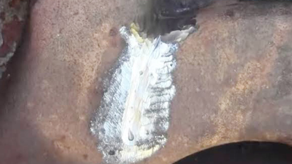
Image by muggyweld
Why Brazing Outperforms Fusion Welding on Exhaust Manifolds
Cast iron exhaust manifolds operate between ambient temperature and well over 1000°F. The graphite flakes that give gray iron its damping properties also create stress risers that propagate cracks under rapid heating and cooling.
Thermal Stress Differences Between Processes
Fusion welding melts the base metal above 2200°F. The heat-affected zone forms brittle carbides and martensite that crack as the casting cools.
Brazing keeps peak temperature below the melting point of the iron, limiting the heat-affected zone and avoiding those phase changes. Residual stresses remain lower, so the joint can expand and contract with the surrounding metal.
Strength and Service Temperature Reality
A properly executed braze with silicon bronze or low-fuming bronze delivers tensile strength in the 40–60 ksi range—adequate for a non-structural manifold that primarily needs gas-tight sealing under vibration. The filler itself must remain solid above the maximum exhaust gas temperature the manifold sees.
Silicon bronze melts near 1780–1880°F; many silver-bearing alloys work near 1150°F. Both stay well above typical manifold skin temperatures while still melting far below the iron.
Surface Preparation Decisions That Control Bond Strength
Contamination and joint geometry decide whether the filler wets the iron or simply sits on the surface.
Crack Arrest and Groove Geometry
Drill a small stop hole at each end of the visible crack to prevent further propagation during heating. Grind a shallow V- or U-groove along the crack—typically 1/16 inch deep and wide enough to accept the filler rod diameter.
Deeper grooves remove more parent metal and weaken thin manifold walls. The groove walls must be bright metal; any residual scale or carbon prevents wetting.
Cleaning Sequence for Oil-Soaked Castings
Exhaust manifolds often contain residual oil, carbon, and rust. Heat the area gently with a soft flame to burn off hydrocarbons, then wire-brush or grind to clean metal. A final wipe with a solvent that leaves no residue improves flux adhesion. Incomplete cleaning is the most common cause of porosity and lack of fusion in brazed manifold repairs.
Filler Metal Selection for Thermal Cycling Service
Not every copper-based rod performs equally under exhaust temperatures and vibration.
Low-Fuming Bronze and Silicon Bronze Options
Low-fuming bronze rods (such as Harris 0 or equivalent) flow readily under a neutral oxy-acetylene flame and produce a strong, ductile deposit. Silicon bronze (ERCuSi-A) works with oxy-fuel, TIG, or MIG processes and offers good strength with lower fuming. Both alloys wet cast iron when the surface is clean and the temperature reaches dull red.
Silver-Bearing Alloys for Lower Heat Input
Certain silver solders formulated for cast iron (working temperature around 1150°F) allow repairs with reduced total heat. These alloys excel at filling tight cracks through capillary action and tolerate less aggressive preheat.
They are more expensive but useful when the manifold geometry limits heat control or when the casting is already thin from prior corrosion.
Flux Requirements
Most bronze and silver rods require flux. Flux-coated rods simplify application; bare rods need dipping or brushing with a borax-based or proprietary flux designed for copper alloys on iron. Flux removes residual oxides and promotes wetting. Insufficient flux produces balling of the filler and weak bonds.
Heat Control and Preheating Strategy
Uneven heating is the fastest way to create new cracks during the repair itself.
Broad Preheat Targets
Preheat a wide zone around the crack—ideally the entire manifold section—to 500–600°F before concentrating heat on the joint. Use a rosebud or large soft flame and keep it moving. Temperature crayons or an infrared thermometer confirm uniformity. The goal is to reduce the thermal gradient when the local brazing temperature is reached.
Working Temperature Indicators
Bring the immediate joint area to a dull red color (roughly 900–1200°F depending on ambient light). At this point the base metal will melt the filler rod on contact. Never heat the iron to bright red or orange; that temperature approaches the range where structural changes begin and increases the chance of warpage or cracking.
Torch Flame Selection
A neutral oxy-acetylene flame is standard. An oxidizing flame can burn the zinc from bronze alloys and leave porous deposits; a carburizing flame introduces carbon and can cause poor flow. Tip size should match the thickness of the manifold wall—typically a #2 to #4 tip for most automotive castings.
Torch Technique and Capillary Flow Execution
Successful brazing relies on the base metal melting the filler, not the torch melting the rod in free air.
Heating and Filler Application Sequence
Heat the groove and surrounding metal until dull red. Touch the fluxed rod to the hot surface; it should melt and flow into the groove by capillary action. Move the torch in small circles to maintain even temperature.
Deposit only enough alloy to fill the groove and form a slight reinforcement. Flow each addition flat before adding more; building a tall bead traps flux and creates stress concentrations.
Multi-Pass Considerations on Longer Cracks
On cracks longer than two inches, work in short segments. Complete one section, allow it to cool slightly while maintaining overall preheat, then move to the next. This staged approach limits the length of the hot zone and reduces the chance of the crack opening further under thermal expansion.
Alternative Processes: MIG and TIG Brazing
Silicon bronze wire can be applied with a MIG spool gun or TIG torch under argon shielding. MIG settings typically start around 18–20 volts and 100–130 amps with 0.030–0.035 inch wire, adjusted for short-circuit transfer that deposits filler without melting the iron.
TIG uses a blunt tungsten and similar filler, offering precise heat control on thin sections. Both methods still require thorough cleaning and controlled overall temperature.
Cooling Protocol and Post-Repair Evaluation
Rapid cooling reintroduces the thermal stresses the process was designed to avoid.
Controlled Cool-Down
After the final deposit, allow the manifold to cool slowly in still air or wrap it in insulating blankets or dry sand. Never quench with water or compressed air. Slow cooling lets residual stresses redistribute and minimizes the formation of hard, brittle zones adjacent to the braze.
Inspection Criteria
Once cool, remove residual flux with a wire brush or light grind. Check for complete wetting along both sides of the groove and absence of porosity or incomplete fill. A pressure or smoke test after reinstallation confirms gas-tight integrity.
Any area that shows lack of fusion must be cleaned and re-brazed; grinding out a failed section and starting over is preferable to leaving a potential leak path.
When Brazing Is Not the Correct Decision
Not every cracked manifold is a candidate for repair.
Structural and Geometric Limits
If the crack has progressed into a mounting flange, runner junction, or thin wall already thinned by corrosion, the remaining cross-section may be insufficient even after a perfect braze.
Multiple interconnected cracks or a manifold that has already been repaired several times often indicate replacement is more economical and reliable.
Material Identification
Confirm the manifold is gray cast iron. Some modern manifolds are ductile iron or stainless steel fabrications; those materials respond differently and may require fusion welding or different fillers. A spark test or simple hardness check can help distinguish common types before committing to a process.
Wrapping Up
Selecting the correct combination of groove preparation, filler alloy, broad preheat, and slow cooling produces a durable seal that accommodates the extreme thermal cycling of an exhaust system.
The advanced insight that separates lasting repairs from temporary ones is recognizing that the braze itself is secondary to heat management: the iron must never experience a steep temperature gradient, either during the repair or during subsequent engine operation.
When that principle governs every decision, a brazed cast iron exhaust manifold returns to service with a high probability of long-term integrity.
Final Thoughts
Can you braze a cast iron exhaust manifold without removing it from the engine?
No. Proper preheat, cleaning, and controlled cooling require the manifold to be off the vehicle. Working in place risks damaging gaskets, wiring, and adjacent components and prevents even heat distribution.
What temperature should the cast iron reach before applying the filler rod?
Heat the joint area to a dull red color, typically in the 900–1200°F range, after a broad preheat of the surrounding metal. The base metal must be hot enough to melt the filler on contact.
Is silicon bronze strong enough for exhaust manifold repairs?
Yes. Silicon bronze provides adequate tensile strength and remains solid well above normal exhaust temperatures while melting below the melting point of cast iron, making it a practical choice for gas-tight, vibration-resistant repairs.
How long does a properly brazed exhaust manifold repair typically last?
When preparation, heat control, and cooling are correct, the repair routinely survives the remaining service life of the engine. Failures almost always trace back to incomplete cleaning, insufficient preheat, or rapid cooling rather than the inherent strength of the braze.