A welder that trips breakers, overloads a generator, or produces an unexpectedly high electric bill almost always points to one overlooked calculation: actual power draw under real operating conditions.
Knowing how to calculate power consumption of a welding machine prevents undersized circuits, inaccurate cost estimates, and thermal shutdowns mid-weld.
Input power differs from output amperage; duty cycle, power factor, and efficiency further separate nameplate numbers from the kilowatt-hours that appear on the utility bill.
Accurate figures let you size generators, select breakers, and forecast operating costs before the first arc is struck. The methods below use only data available on the machine nameplate or in the manual.

Image by ecoflow
Reading the Nameplate Data Correctly
Every calculation starts with the rating plate. Misreading these values produces errors larger than any later adjustment for duty cycle or efficiency.
Input Voltage, Current, and Phase Identification
Locate the primary input specifications: rated input voltage (commonly 120 V, 208–240 V, or 460 V), maximum input current (often labeled I1max or “Amps Input at Rated Output”), and phase (1-phase or 3-phase). Single-phase machines list one current value; three-phase units list current per line.
Idle or standby current is usually far lower and is irrelevant for load calculations. Use the current listed at the rated output and duty cycle that matches your intended work.
Duty Cycle and Rated Output Relationship
Duty cycle is expressed as a percentage of a 10-minute period. A 200 A machine rated 60 % duty cycle can deliver 200 A for 6 minutes and must cool for 4 minutes.
The same machine may offer higher duty cycle at reduced output (for example, 100 % at 130 A). Record both the amperage and the corresponding duty cycle; later average-power calculations depend on this pair.
Core Formulas for Input Power
Real power is the quantity that determines energy consumption and heat generation in cables and breakers.
Single-Phase Calculation
For single-phase machines the real input power in watts is:
where is input voltage, is input current, and is power factor (decimal). Convert to kilowatts by dividing by 1 000. When power factor is unknown, a conservative estimate of 0.85 for older transformer machines or 0.95 for modern inverter machines with power-factor correction yields usable results.
Example: 240 V × 40 A × 0.90 = 8 640 W = 8.64 kW.
Three-Phase Calculation
Three-phase power uses the line-to-line voltage and the line current:
Again divide by 1 000 for kilowatts. The factor (approximately 1.732) accounts for the three-phase relationship. Example: 480 V × 30 A × 0.90 × 1.732 ≈ 22.4 kW.
Accounting for Power Factor
Power factor is the ratio of real power (kW) to apparent power (kVA). Conventional inverters without correction often operate near 0.65–0.75; machines with active PFC reach 0.95–0.99.
Lower power factor increases the current drawn for the same real power and therefore increases cable and transformer loading even though the utility bill (which charges for kWh) reflects only real power. Always prefer measured or nameplate PF when available.
Converting Output Settings to Input Consumption
When input current is not listed, approximate it from welding output parameters.
Using Efficiency Ratings
Arc power equals output voltage times output current. Divide that product by machine efficiency to obtain estimated input power:
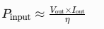
Inverter efficiency typically ranges from 0.85 to 0.92; older transformer machines may fall between 0.70 and 0.80. Example: 28 V × 200 A = 5 600 W arc power. At 88 % efficiency the input power is approximately 6.36 kW. This method is useful for quick checks but remains secondary to nameplate input data.
Factoring Duty Cycle into Average Power Use
Continuous full-load operation is rare. Average power over a working period equals instantaneous power multiplied by the actual fraction of arc-on time.
If a machine draws 9 kW while welding and the operator maintains a 40 % arc-on time (typical for stick or short-circuit MIG fabrication), average power is 9 kW × 0.40 = 3.6 kW.
For a 10-minute rated duty cycle of 60 %, the thermal limit itself already embeds a 0.60 factor when the machine is run at its rated output; actual shop duty cycle is often lower.
Use the lower of the two values—machine rating or observed arc-on percentage—for cost and generator sizing.
Calculating Energy Cost in kWh and Dollars
Energy consumed equals average power in kilowatts multiplied by operating hours:
Multiply by the local electricity rate ($/kWh) to obtain cost. Example: 3.6 kW average × 4 hours × $0.14/kWh = $2.02. Idle consumption (fans and controls) is usually under 200 W and can be ignored for short sessions or added separately for continuous shop use.
Practical Examples for Common Machines
200 A Class Inverter MIG or Multi-Process
Typical nameplate: 240 V single-phase, 30–35 A input at rated output, 60 % duty cycle, PF ≈ 0.95. Peak input power ≈ 240 × 33 × 0.95 ≈ 7.5 kW. At 40 % actual arc-on time average power falls to about 3 kW. Four hours of intermittent work consumes roughly 12 kWh.
250 A Stick or Heavy MIG
Nameplate often shows 240 V, 45–50 A input. Peak power approaches 11–12 kW. With stick welding’s lower duty factor (25–35 % because of electrode changes and slag removal) average power may be only 3–4 kW, yet circuit and generator sizing must still accommodate the peak.
Compact 120 V Machines
A 140 A unit on a 20 A, 120 V circuit draws near the circuit limit (approximately 2.0–2.4 kW). Duty cycle is usually low (20–30 %). These machines are practical only for short beads; continuous use quickly exceeds both thermal and circuit limits.
Generator and Circuit Sizing Decisions
Generator capacity must cover peak input power plus a margin for starting and voltage regulation. Convert calculated kilowatts to kVA by dividing by generator power factor (commonly 0.8). A machine that draws 8 kW real power therefore needs at least 10 kVA of generator capacity, preferably 20–25 % more for clean inverter operation.
Circuit breakers and conductors are sized from the maximum input current listed on the nameplate, not from average power. NEC Article 630 provides specific demand factors for welders that can reduce calculated feeder loads when multiple machines share a circuit, but individual branch circuits are normally protected at 100 % of the welder’s rated input current.
Wraping Up
Accurate power-consumption figures decide whether an existing 50 A receptacle is adequate, whether a generator must be upgraded, and how much a fabrication project will add to the monthly electric bill.
The decisive step is always to begin with nameplate input voltage and current, apply power factor and observed duty cycle, and only then convert to kilowatt-hours or generator kVA.
Advanced shops further refine the calculation by logging actual arc-on time with a simple timer or data-logging clamp meter; the resulting measured average power often reveals that shop practice runs well below the machine’s thermal limit, freeing capacity for additional equipment on the same feeder.
FAQs
How many kWh does a 200 amp welder use per hour?
At full rated output a typical 200 A inverter draws 7–8 kW. With a realistic 40 % arc-on time the average consumption is approximately 3–3.2 kWh per hour of shop time.
Does duty cycle reduce the power a welder draws from the outlet?
No. Duty cycle limits continuous welding time to prevent overheating; while the arc is on, the machine still draws near its full rated input power. Average power over a longer period is lower because of the cooling intervals.
How do I calculate generator size for a welding machine?
Take the peak real input power in kW, divide by 0.8 (typical generator power factor), then add 20–25 % margin. An 8 kW welder therefore needs a generator rated at least 12–13 kVA.
What is the difference between input amps and welding amps?
Welding amps are the output current delivered to the electrode or wire. Input amps are the current drawn from the supply circuit and are always lower than output amps because of the voltage transformation and machine efficiency.