Choosing the wrong current for a given plate thickness is one of the fastest ways to ruin a stick weld. On thin material the electrode burns through in seconds; on thick plate the bead sits on top with zero fusion.
Matching stick welding amperage for metal thickness is the single most important decision after electrode selection, because heat input controls penetration depth, bead profile, and the risk of distortion or cracking.
Incorrect settings waste electrodes, create rework, and compromise joint strength on everything from trailer frames to structural steel. This guide delivers exact starting ranges, electrode-to-thickness pairings, and the adjustments that separate usable welds from scrap.
How Metal Thickness Directly Dictates Amperage Choice
Thickness determines both the heat sink capacity of the base metal and the amount of fusion needed for a sound joint. Thin sections lose heat rapidly and require lower current to stay below the burn-through threshold. Thick sections absorb heat and demand higher amperage plus larger electrodes to achieve full penetration or proper multi-pass fill.
Thin Material Decisions (Under 1/8 Inch)
For 16-gauge to 1/8-inch mild steel, stay with 3/32-inch electrodes and the lower half of their published ranges. Typical settings fall between 40–90 A depending on electrode type. Travel speed must increase and arc length must stay short; any excess heat quickly produces holes or excessive warping.
Single-pass fillet or lap joints are preferred; open-root butts on this thickness are difficult with stick and often require specialized technique or a process change.
Medium Thickness Range (1/8 to 1/4 Inch)
This is the most common fabrication window. 1/8-inch electrodes dominate, with amperage typically 80–140 A. At 3/16-inch plate a 1/8-inch 7018 or 6013 at 110–130 A produces reliable fusion in flat and horizontal positions.
Multi-pass work begins to appear on open butts; the root pass often runs slightly hotter than subsequent fill passes to ensure complete penetration without excessive reinforcement.
Thick Plate Requirements (Over 1/4 Inch)
Above 1/4 inch the heat sink grows rapidly. 5/32-inch electrodes become standard, pushing amperage into the 130–220 A band for 7018. Bevel preparation is almost always required for full-penetration joints. Multi-pass sequences with controlled interpass temperature keep residual stresses manageable.
On 3/8-inch and thicker plate, 3/16-inch electrodes at 180–275 A improve deposition rate once the root is established.
Electrode Diameter and Amperage Pairing by Thickness
Electrode diameter sets the maximum practical amperage and the minimum metal thickness that can be welded without excessive burn-through risk. A useful field starting point is approximately one amp per 0.001 inch of electrode diameter in the flat position, then adjusted for actual conditions.
Common Electrode Amperage Ranges
| Electrode | 3/32″ Diameter | 1/8″ Diameter | 5/32″ Diameter | 3/16″ Diameter |
|---|---|---|---|---|
| E6010 / E6011 | 40–85 A | 75–125 A | 110–165 A | 140–210 A |
| E6013 | 40–90 A | 80–130 A | 105–180 A | 150–230 A |
| E7018 | 70–110 A | 90–160 A | 130–220 A | 200–275 A |
| E7014 | 80–125 A | 110–165 A | 150–210 A | 200–275 A |
These ranges are manufacturer mid-points compiled from multiple sources. Always verify against the specific electrode packaging.
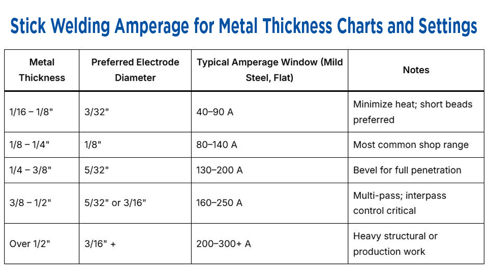
Matching Rod Size to Plate Thickness
| Metal Thickness | Preferred Electrode Diameter | Typical Amperage Window (Mild Steel, Flat) | Notes |
|---|---|---|---|
| 1/16 – 1/8″ | 3/32″ | 40–90 A | Minimize heat; short beads preferred |
| 1/8 – 1/4″ | 1/8″ | 80–140 A | Most common shop range |
| 1/4 – 3/8″ | 5/32″ | 130–200 A | Bevel for full penetration |
| 3/8 – 1/2″ | 5/32″ or 3/16″ | 160–250 A | Multi-pass; interpass control critical |
| Over 1/2″ | 3/16″ + | 200–300+ A | Heavy structural or production work |
The electrode should generally be no larger than the thinnest member of the joint and ideally smaller than half the thickness for thin material.
Position-Specific Amperage Adjustments
Gravity and puddle control force amperage changes once the weld leaves the flat position. The same electrode and thickness combination rarely runs at identical current across all positions.
Flat and Horizontal Settings
Use the middle-to-upper portion of the electrode range. Higher current increases deposition rate and improves wetting on clean plate. Horizontal fillets often run 5–10 A lower than pure flat to control the upper toe and avoid undercut.
Vertical-Up Requirements
Reduce current 10–20 % from the flat setting. A 1/8-inch 7018 that runs at 125 A flat typically drops to 105–115 A for vertical-up. The lower heat keeps the slag from running ahead of the puddle and allows a controlled shelf technique or triangular weave.
Vertical-down is rarely used with low-hydrogen electrodes and is limited to certain cellulose rods at higher travel speeds.
Overhead Considerations
Overhead usually sits between flat and vertical settings—often 5–10 % below flat. Arc length must remain extremely short to support the molten metal against gravity. Excess current produces dripping slag and incomplete fusion at the toes.
Polarity and Power-Source Influence on Thickness Matching
Polarity changes heat distribution and therefore the effective amperage felt by the joint.
DCEP Advantages for Most Thicknesses
Direct-current electrode positive concentrates roughly two-thirds of the arc heat at the workpiece. This improves penetration on medium and thick plate and is the preferred polarity for 6010, 6011, and 7018. On thin material the same polarity still works, but operators must stay at the low end of the range and increase travel speed.
AC Operation and Compensation
AC machines require a modest increase—typically 5–15 %—to achieve comparable arc stability and penetration. Older transformer “buzz boxes” often lack fine control, so operators start higher and compensate with technique. Modern inverter machines with AC output and dig control narrow the gap between AC and DC performance.
Joint Preparation and Fit-Up Effects on Required Amperage
Amperage charts assume reasonably good fit-up. Real joints deviate.
Open-Root and Beveled Joints
Open-root butts on thicker plate often need a hotter root pass (upper end of the range or a cellulose electrode) followed by cooler fill passes. Bevel angle and root opening directly influence the current needed for keyhole control or full fusion without burn-through.
Fillet and Lap Joints
These configurations tolerate a wider amperage band because the joint itself acts as a heat sink. A 1/4-inch fillet on 3/8-inch plate can often run 10–15 A lower than a comparable butt joint while still achieving adequate throat thickness.
Diagnosing Amperage Errors from Bead and Arc Behavior
Visual and auditory feedback arrives faster than any meter once the arc is established.
Signs of Insufficient Amperage Relative to Thickness
The electrode sticks repeatedly, the arc extinguishes easily, the bead is tall and ropey, and slag freezes tightly to the surface. On thick plate the result is incomplete fusion at the root or toes. Increase current in 5 A increments until the arc stabilizes and the slag lifts cleanly after cooling.
Signs of Excessive Amperage Relative to Thickness
The electrode coating glows red beyond the arc, spatter becomes heavy, undercut forms along the toes, and the bead flattens excessively. On thin material the immediate result is burn-through.
Reduce current and increase travel speed simultaneously; simply dropping amperage without adjusting speed often leaves a cold-looking but still undercut bead.
Multi-Pass Strategy and Heat Input Control on Thick Sections
On plate thicker than 1/4 inch the total heat input across all passes becomes as important as the amperage of any single pass.
Root passes frequently run hotter to ensure penetration. Fill and cap passes drop 10–20 A to control bead shape and interpass temperature. For low-hydrogen electrodes on restrained joints, interpass temperature is typically held between 200–400 °F depending on steel grade and code requirements.
Excess heat accumulation raises the risk of hydrogen cracking even when individual bead amperage is correct.
Real-World Decision Process for Selecting Final Settings
Begin with the electrode manufacturer’s published range for the chosen diameter and polarity. Select the mid-point for the intended position and thickness. Run a test bead on scrap of identical thickness and joint geometry.
Evaluate fusion by sectioning or by grinding a face and checking for incomplete penetration. Adjust in 5 A steps while recording travel speed and arc length.
Once the bead profile, slag release, and sound match the target, lock the setting. Document ambient temperature, machine type, cable length, and electrode lot—these variables shift effective amperage on the next job.
Wrapping Up
Matching stick welding amperage to metal thickness is a balance of electrode capability, heat sink, position, and joint geometry. Charts supply the starting window; the puddle and the finished bead supply the final answer.
Advanced operators further refine results by combining short-arc technique with deliberate stringer sequencing rather than wide weaves, preserving mechanical properties and minimizing residual stress on high-restraint joints.
FAQs
What amperage for 1/4 inch steel with stick welding?
For 1/4-inch mild steel, a 1/8-inch 7018 typically runs 110–140 A in the flat position; a 5/32-inch electrode moves into the 140–180 A range. Start mid-range and adjust for position and fit-up.
How many amps for 1/8 inch metal stick welding?
Use a 3/32-inch or 1/8-inch electrode at 70–120 A depending on type. Stay toward the low end of the range and maintain a short arc to avoid burn-through.
Does welding position change amperage for the same thickness?
Yes. Reduce 10–20 % from the flat setting for vertical-up and roughly 5–10 % for overhead to maintain puddle control.
What rod size and amps for 3/8 inch plate?
A 5/32-inch 7018 at 150–200 A is common for multi-pass work. Bevel the joint and control interpass temperature.