
Plastic repair can fail quickly when the wrong heat source, temperature, or filler material is used. What is hot air plastic welding, and how does it differ from simply heating or melting plastic? Hot air plastic welding uses a controlled stream of heated air to soften compatible thermoplastic surfaces and, when required, a matching filler rod so the materials can fuse into a solid joint.
The process is useful for repairing plastic panels, tanks, pipes, bumpers, and fabricated components where conventional welding methods are unsuitable.
Proper temperature control is critical because insufficient heat can produce a weak bond, while excessive heat can burn, deform, or degrade the plastic.
Understanding how hot air plastic welding works, which plastics can be welded, and how heat and filler selection affect joint quality provides a practical foundation for making reliable plastic repairs.
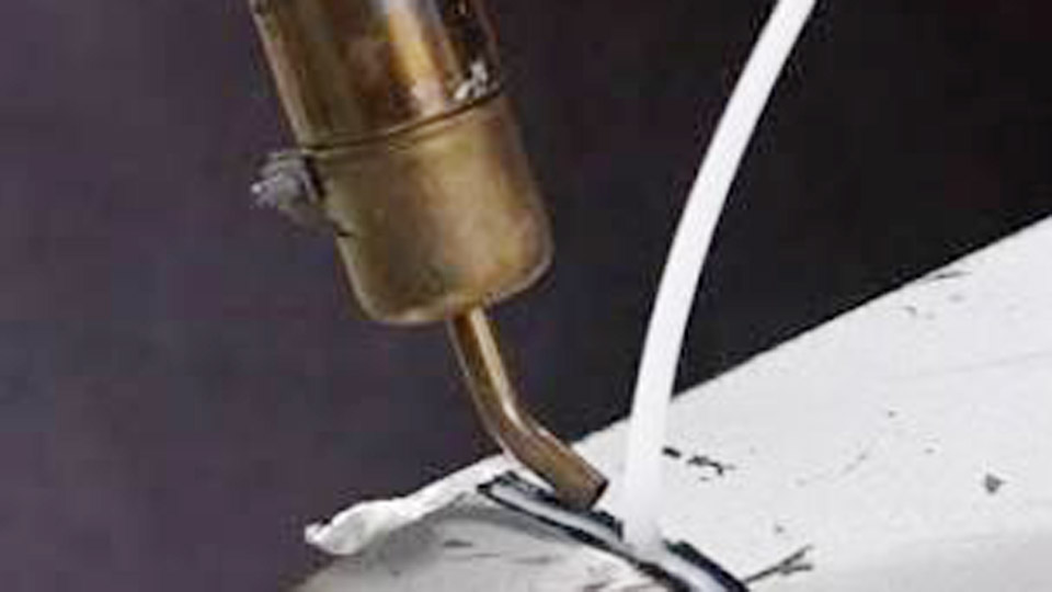
Image by polyvanceofficial
How Hot Air Softens and Fuses Thermoplastics at the Molecular Level
Hot air (also called hot gas) welding works only on thermoplastics. These materials soften when heated because their molecular chains become mobile; thermosets cannot be welded this way because cross-links prevent chain mobility.
Role of Hot Gas Temperature Relative to Material Melting Point
The air stream temperature is typically set 80–100 °C above the melting or softening point of the specific polymer. This range ensures both the substrate surface and the filler rod reach a plastic state without degrading the polymer chains.
Measuring temperature 5 mm inside the nozzle with a thermocouple gives the most consistent reading. Excess heat causes discoloration, bubbling, or chain scission that weakens the joint; insufficient heat produces only surface adhesion with no interdiffusion.
Pressure and Molecular Interdiffusion Requirements
Once the surfaces are softened, pressure forces the mobile chains to interdiffuse across the interface. Typical force applied through a speed-welding nozzle toe or manually on the rod ranges from 15–30 N (approximately 1.5–7.5 lb depending on rod diameter).
Without adequate pressure the molecules do not entangle, leaving voids or a cold joint that fails under load or chemical exposure.
Correct Temperature and Airflow Ranges for Common Plastics
Temperature and airflow must match the polymer grade, thickness, and ambient conditions. Values below follow DVS 2207-3 guidelines for speed-welding nozzles and serve as starting points; always verify with a test coupon of the actual material.
| Material | Hot-Gas Temperature (°C) | Temperature (°F) | Airflow (l/min) | Pressure on Ø3 mm Rod | Pressure on Ø4 mm Rod |
|---|---|---|---|---|---|
| HDPE | 300–350 | 572–662 | 40–50 | 2.0–3.5 lb | 5.5–7.5 lb |
| LDPE | 260–320 | 500–608 | 40–50 | 2.0–3.5 lb | 5.5–7.5 lb |
| PE (general) | 280–330 | 536–628 | 40–50 | 2.0–3.5 lb | 5.5–7.5 lb |
| PVC-U | 320–370 | 608–698 | 40–50 | 1.5–2.5 lb | 3.5–5.5 lb |
| Flexible PVC | 320–370 | 608–698 | 40–50 | 1.0–1.5 lb | 1.5–2.5 lb |
| CPVC | 350–400 | 662–752 | 40–50 | 3.5–4.0 lb | 4.0–5.5 lb |
| PMMA | 320–370 | 608–698 | 40–50 | 2.5–3.5 lb | 4.0–6.5 lb |
| PVDF | 350–400 | 662–752 | 40–50 | 2.5–4.0 lb | 5.5–7.5 lb |
PVC and CPVC Settings for Chemical and Structural Service
Rigid PVC-U tolerates a relatively wide window of 320–370 °C. CPVC requires the higher end (350–400 °C) because of its elevated heat resistance. Travel speed must drop slightly on CPVC so the thicker melt zone has time to form.
Both materials demand clean, dry air; oil or moisture in the stream creates porosity that chemical tanks cannot tolerate.
Polyethylene Grades and the Need for Matching Melt Flow
HDPE and LDPE differ enough in crystallinity that a single temperature setting fails. HDPE needs 300–350 °C while LDPE stays cooler at 260–320 °C. Using the wrong grade of filler rod relative to the sheet produces a weld whose strength falls well below the parent material even if the temperature looks correct.
Polypropylene and ABS Temperature Windows
PP typically runs near 300–350 °C. ABS, being amorphous, softens more gradually and often works between roughly 350 °C nozzle temperature and lower values depending on the exact formulation. Overheating ABS quickly produces visible browning and loss of impact resistance.
Choosing Between Pendulum and Speed Welding Techniques
The choice of technique is driven by joint length, access, and required deposition rate rather than personal preference.
When Restricted Access or Short Welds Demand Pendulum Motion
Pendulum (fan) welding uses a round nozzle moved in a continuous oscillating pattern while the free hand feeds the rod at approximately 45°. It suits tight corners, short repairs, or irregular geometry where a rigid speed nozzle cannot follow the path. Travel speed remains low—typically 0.1–0.2 m/min—so heat input stays controlled.
Long Straight Seams and High-Production Speed Nozzles
Speed welding employs a specialized nozzle whose toe rides on the rod and applies consistent downward force. The gun travels in a straight line at 0.2–0.3 m/min or higher once the operator is proficient.
This method is the standard for tank fabrication, ducting runs, and long membrane seams because deposition rate and bead uniformity improve markedly.
Filler Rod Selection and Joint Preparation Decisions
Rod and joint geometry control the final load-bearing capacity more than any other single variable after temperature.
Matching Rod Diameter and Profile to Thickness
Most structural work uses 3 mm or 4 mm round or triangular rods of identical polymer and grade to the substrate. Thicker sections may require multiple passes or a larger rod.
Air bubbles trapped inside the rod during manufacture become voids in the finished weld; visual inspection of the rod before use prevents this defect.
Bevel Angle and Surface Cleaning for Structural Strength
Edges thicker than approximately 3–4 mm receive a 30–60° single or double V-bevel so the rod can penetrate the full thickness.
The weld zone must be scraped or abraded to remove the oxidized or contaminated surface layer; residual mold-release agents, dirt, or UV-degraded material prevent fusion even at correct temperature. Tacking with a dedicated tacking nozzle holds the joint alignment before the full weld is deposited.
Key Process Variables That Determine Final Weld Strength
Temperature, pressure, speed, and gun position interact continuously; changing one forces adjustment of the others.
Travel Speed Windows Linked to Airflow and Rod Feed
At the recommended airflow of 40–50 l/min, travel speeds between 0.1 and 0.3 m/min keep the melt zone ahead of the rod without overheating the already-deposited material. Faster travel leaves incomplete fusion; slower travel raises the risk of thermal degradation and excessive bead height.
Gun Angle and Nozzle Distance Effects
The nozzle is held so the air stream simultaneously heats the groove root and the advancing tip of the rod. Typical distance is 5–10 mm.
A steeper angle concentrates heat on the substrate; a shallower angle favors the rod. Consistent angle maintains uniform melt depth along the entire seam.
Equipment Features That Affect Consistency on the Job
Hand-held guns with separate remote blowers allow firmer grip and more stable pressure application than integrated-fan units. Digital temperature displays and thermocouple ports reduce the variability that occurs when ambient temperature or cable voltage drop changes output.
Interchangeable nozzles (tacking, round, speed) cover the full range of joint types without changing tools. Clean, dry air—whether from a dedicated blower or filtered compressed air—is non-negotiable; moisture or oil produces porosity that no amount of pressure can eliminate.
Wrapping Up
Selecting the correct hot-air parameters begins with identifying the exact polymer grade, measuring actual nozzle temperature, and confirming fusion on a scrap coupon before production welding.
Once temperature, pressure, and speed produce a shiny, continuous bead with clean toe fusion and no discoloration, the joint can be expected to deliver the design strength required for chemical containment, structural fabrication, or membrane integrity.
Advanced operators further improve consistency by recording ambient temperature, airflow setting, and exact nozzle-to-work distance for each material lot, turning an inherently manual process into a repeatable, documented procedure.
FAQs
What temperature should I set for hot air welding PVC?
Start at 320–370 °C (608–698 °F) measured 5 mm inside the nozzle with 40–50 l/min airflow. Adjust based on a test weld; rigid PVC-U prefers the middle of the range.
Can hot air welding be used on polyethylene tanks?
Yes. HDPE tanks weld at 300–350 °C with matching HDPE rod. Surface scraping and correct pressure are required to achieve structural strength.
What is the difference between pendulum and speed hot air welding?
Pendulum uses a round nozzle with oscillating motion for short or restricted joints. Speed welding uses a specialized nozzle that applies continuous pressure and travels in a straight line for long production seams.
How much pressure is needed on the welding rod?
Typical force is 15–30 N overall, or 1.5–3.5 lb on a 3 mm rod and higher on 4 mm rods, applied through the speed-nozzle toe or by hand.


