Removing factory body panels starts with knowing how to drill out spot welds on a car without damaging the metal you plan to keep. Unlike cutting or grinding, drilling targets only the weld itself, preserving the underlying panel for a cleaner repair and more accurate fit-up.
Poor technique can leave oversized holes, thin the base metal, or increase distortion, leading to additional fabrication time and weaker replacement welds.
Whether you’re performing rust repair, collision restoration, or panel replacement, proper spot weld removal is a critical first step that affects the quality of the entire job.
Mastering the correct tools, drilling depth, and separation methods allows you to work more efficiently while protecting the vehicle’s structural integrity and reducing unnecessary rework.
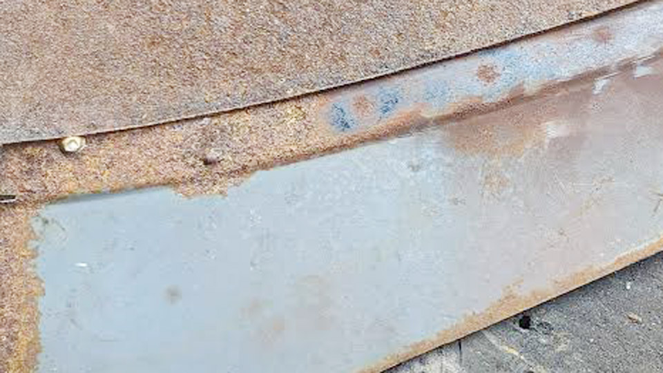
Image by thedrive
Why Spot Weld Removal Matters in Auto Body Work
Modern unibody construction relies on hundreds of spot welds for rigidity and crash performance. Incorrect removal weakens joints or creates oversized holes that complicate rewelding. Proper drilling isolates the nugget from the top sheet without penetrating the base layer, maintaining alignment and structural integrity.
Understanding Spot Weld Characteristics
Spot welds form a hardened nugget, typically 5–9 mm in diameter, fusing two or more sheets. On cars, they appear as dimples or slight raised circles along seams, wheel arches, rockers, doors, and quarters.
Older vehicles often use smaller 5–6 mm welds; modern ones standardize around 6–8 mm. High-strength steels (HSLA or AHSS, including boron) in safety structures demand adjusted techniques to avoid cracking or excessive work-hardening.
Panel thickness, coatings (galvanized or e-coat), rust, and paint layers affect difficulty. Galvanized zinc can smear and accelerate bit wear, while rust hides weld locations and dulls edges quickly.
Common Challenges in Automotive Applications
Access in tight areas like door hems or underbody rails limits drill angles. Over-drilling risks holes in the base panel, requiring filler or patch work. Heat buildup in thin metal causes warping, and off-center cuts leave residual weld material that prevents clean separation.
Essential Tools and Equipment for Spot Weld Drilling
Tool choice directly impacts speed, cleanliness, and panel preservation. Generic twist drills often wander or cut too aggressively.
Spot Weld Cutters vs. Standard Drill Bits
Dedicated spot weld cutters (hole-saw style with pilot pins) cut a clean ring around the nugget perimeter, separating the top sheet while leaving most of the weld on the base. Flat-end designs or those with depth control excel here. Standard HSS twist bits work in a pinch but require more skill to avoid breakthrough.
Recommended sizes:
- 6 mm (or 1/4″) for smaller/older welds.
- 8 mm (5/16″) for most modern automotive applications.
- Up to 3/8″ (9.5 mm) for larger or stubborn welds.
Double-sided or reversible cutters extend life. Cobalt (M35/M42) or TiN/TiAlN-coated bits handle hardened nuggets better than plain HSS.
Supporting Tools and Accessories
- Center punch: Automatic or manual for precise dimpling.
- Pilot bits: 1/8″ (3.2 mm) for initial centering.
- Variable-speed drill: Corded preferred for consistent torque; 500–1,200 RPM range.
- Cutting fluid/lubricant: Essential for heat reduction and chip evacuation.
- Panel separator/chisel: For post-drill separation (e.g., Lisle 51900 or air hammer with seam buster).
- Grinder/sander: For cleanup and rust removal.
- Depth stops or collars: On advanced setups to limit penetration.
Pneumatic spot weld drills with auto-advance and backing hooks suit high-volume work, offering precise depth control.
Material-Specific Tool Considerations
For mild steel: Cobalt HSS at moderate speeds. Galvanized: Coated bits to resist zinc buildup. UHSS/boron: Carbide-tipped or switch to grinders/file belts, as drills wear rapidly.
Preparing the Work Area and Locating Welds
Effective removal starts with visibility and access.
Surface Preparation Techniques
Wire brush, flap disc, or grinder to remove paint, seam sealer, rust, and undercoating. This reveals dimples clearly and prevents bit contamination. Mark welds with a paint marker or scribe for reference. Clean both sides where possible to reduce zinc or debris issues.
Identifying and Marking Weld Locations
Look for regular patterns along factory seams—typically 30–80 mm spacing. Use a magnet or light to differentiate from dimples caused by dents. On rusted panels, tap lightly to confirm. Center punch each marked spot firmly to create a stable starting dimple that prevents bit walk.
Drilling Techniques and Best Practices
Execution separates clean jobs from rework.
Step-by-Step Drilling Process
- Secure the panel if possible to minimize vibration.
- Pilot drill with a small bit (1/8″) through the center punch mark.
- Apply cutting fluid generously.
- Switch to spot weld cutter. Align pilot pin in the hole.
- Set drill to 500–1,000 RPM (lower for harder steels: 500–800 RPM for AHSS).
- Apply steady, moderate pressure. Use slight side-to-side rocking motion to maintain cutting action.
- Stop immediately when resistance drops or the bit “breaks through” the top sheet (usually 1–2 mm depth). Feel for the give.
Do not force; let the cutter work. Pause to clear chips and re-lubricate.
RPM, Feed, and Pressure Guidelines
| Material Type | Recommended RPM | Notes |
|---|---|---|
| Mild Steel | 800–1,200 | Standard panels |
| Galvanized | 700–1,000 | Watch for zinc smear |
| HSLA | 600–900 | Moderate pressure |
| AHSS/Boron | 500–800 | Or prefer grinding |
Reduce pressure near breakthrough for control. Depth stops or tape markings help on manual setups.
Alternative Removal Methods
Grinding/Sanding: Die grinder with cutoff wheels or file belts (e.g., 3M) for tight spots or hard steels. Effective but generates more dust and heat.
Air Hammer/Seam Buster: After pilot access, for faster panel separation in accessible areas. Less precise but efficient for volume.
Plasma Gouging: Advanced option for speed on production work, minimizing mechanical stress.
Choose based on access, material, and panel value.
Post-Drilling Cleanup and Panel Separation
Removing Residual Weld Material
After drilling, use a flat chisel, panel popper, or air hammer to pry sheets apart gently. The top panel should lift with the nugget mostly remaining on the base. Grind or burr any protruding weld remnants flush without thinning the metal.
Surface Finishing for Rewelding
Deburr holes, remove all slag, rust, and coatings with a grinder and wire wheel. Acetone wipe for cleanliness. For plug welding later, holes should be 6–8 mm—match your drill size. Apply weld-through primer if galvanized protection is needed.
Rewelding Considerations After Spot Weld Removal
Drilling creates opportunities for stronger MIG plug welds or seams. Match OEM spacing and test settings on scrap. Clamp tightly to control gaps. Use shunting techniques if needed for consistent current flow on repairs.
Hole Preparation and Weld Settings
Clean edges ensure fusion. For 0.8–1.0 mm steel, typical MIG settings: short-circuit or pulse mode, 0.023–0.030″ wire, appropriate voltage/wire speed. Stitch or plug as required. Grind welds flush only after verifying strength.
Advanced Techniques for Challenging Scenarios
Working with Modern High-Strength Steels
Boron and AHSS require carbide tools or abrasive methods to avoid rapid dulling and heat-affected zone weakening. Lower RPM and minimal pressure preserve properties. Consult OEM repair manuals for specific panel replacement procedures.
Tight Access and Multi-Layer Stacks
Use right-angle drills, flexible extensions, or belt sanders. For three-layer stacks, drill incrementally and verify each interface. Pneumatic tools with backing arms excel here.
Minimizing Distortion on Thin Panels
Work in small sections, alternate sides, and use heat sinks or frequent cooling. Proper lubrication and controlled feed reduce input.
Common Technical Decisions and Trade-offs
- Bit Life vs. Cost: Cobalt sets last longer; factor replacement frequency for large jobs.
- Precision vs. Speed: Cutters for restoration; grinders for collision where time matters.
- Depth Control: Manual feel vs. dedicated pneumatic drills—choose based on volume and panel value.
Wrapping Up
Successful spot weld removal balances tool capability with operator technique and material awareness. On a quarter panel replacement, precise drilling preserves factory alignment points, enabling stronger plug welds that restore or exceed original strength.
The pro-level takeaway is treating each weld as part of the overall joint strategy—clean separation today means fewer compromises in the final weldment. Prioritize panel preservation over speed for structural repairs.
FAQ
What size drill bit is best for most car spot welds?
An 8 mm (5/16″) spot weld cutter handles the majority of modern automotive welds effectively. Use 6 mm for smaller older welds. Match closely to nugget diameter to avoid oversized holes.
How do you prevent drilling through the bottom panel?
Center punch accurately, use a pilot hole, apply moderate pressure, and stop at the first drop in resistance. Depth stops, flat cutters, or pneumatic drills with adjustment provide extra insurance.
Can you remove spot welds without a special cutter?
Yes—pilot with a small bit then enlarge carefully with a twist bit slightly larger than the weld, or use grinders/sanders. Results are less clean and require more skill to protect the base metal.
What’s the best way to handle rusty or galvanized panels?
Clean thoroughly first. Use cutting fluid liberally on coated bits. For heavy rust, consider air hammer separation after initial access.