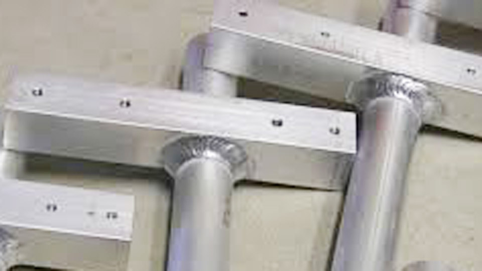
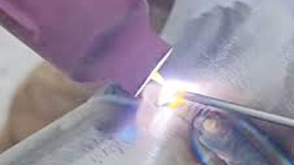
TIG welding aluminum presents unique challenges due to its high thermal conductivity, low melting point around 1,200°F, and tenacious oxide layer that melts at nearly 4,000°F. Many welders struggle with inconsistent puddles, porosity, or lack of fusion when first tackling aluminum with TIG.
Mastering TIG welding aluminum techniques requires precise control of AC settings, torch manipulation, and material preparation to achieve strong, clean welds that perform in real-world applications like fabrication, repairs, and structural work.
I’ll discuss practical, high-density information on parameters, equipment choices, and execution decisions that directly impact weld quality.
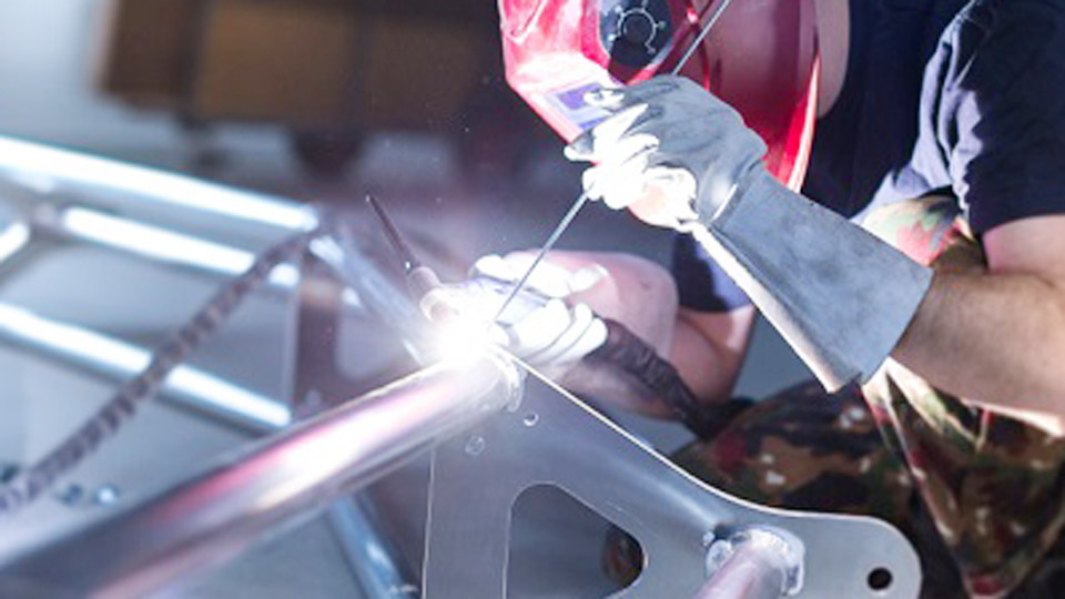
Image by westermans
Why TIG for Aluminum?
TIG (GTAW) excels on aluminum because it provides superior arc control, minimal spatter, and the ability to produce high-quality, visually appealing welds without flux.
Unlike MIG, TIG allows precise heat management critical for thin sections prone to distortion or burn-through. Professionals choose it for applications demanding x-ray quality or post-weld anodizing compatibility.
Material Properties Driving Technique Choices
Aluminum’s rapid heat dissipation demands higher initial amperage than steel, yet its quick melting requires fast travel speeds and foot pedal modulation. The oxide layer necessitates AC polarity for cleaning.
Alloy selection matters: 6061-T6 is common but crack-sensitive in certain joints, while 5XXX series offers better strength and corrosion resistance. Always match or select filler based on service requirements rather than defaulting to one type.
Equipment Setup for TIG Welding Aluminum
Successful aluminum TIG starts with machine capabilities and consumables tuned to the job.
Power Source and Polarity Requirements
Use an AC/DC inverter TIG welder with adjustable AC balance and frequency. DCEN lacks oxide-cleaning action and is unsuitable for standard aluminum work. Inverters outperform older transformers by offering precise waveform control, higher efficiency, and better low-amperage stability for thin material.
Key features to prioritize:
- AC balance control (EN/EP ratio)
- AC frequency adjustment (20–250 Hz)
- Pulse capability for thin stock
- High-frequency (HF) start to avoid tungsten contamination
Tungsten Electrode Selection and Preparation
For AC aluminum:
- Pure tungsten (green): Traditional choice that forms a stable ball naturally.
- Zirconiated (white/grey): Excellent ball retention and current capacity.
- 2% Lanthanated (blue): Versatile for AC/DC, handles higher amperage, and provides stable starts; a strong all-around option.
Diameter guidelines (approximate for AC):
- Up to 100A: 3/32″
- 100–200A: 1/8″
- 200A+: 5/32″ or 3/16″
Prepare by grinding a blunt taper or point (20–30° for lanthanated). On AC, a small ball forms naturally—avoid oversized balls that cause arc wander. Never use thoriated (red) for primary aluminum work.
Shielding Gas and Flow Rates
100% argon is standard for most applications, delivering excellent arc stability and cleaning. Use argon/helium mixes (e.g., 75/25) for thicker sections (>1/4″) to increase heat input and penetration without excessive amperage.
Flow rates (CFH, adjust for cup size and drafts):
- #5–#6 cup: 15–20 CFH
- #7–#8 cup: 20–25 CFH
- Higher for windy conditions or larger cups (use gas lens for better coverage)
Pre-flow 5–10 seconds and post-flow 10–15+ seconds protect the tungsten and cooling puddle. Excessive flow causes turbulence and porosity.
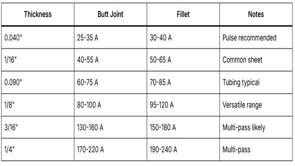
Amperage and Thickness Guidelines
The rule of thumb—roughly 1 amp per 0.001″ of thickness—provides a starting point but requires adjustment for joint type, position, alloy, and heat sinking. Inverters often run 10–15% lower effective amperage.
Settings by Thickness Table
| Thickness | Amperage (AC) | Tungsten | Filler Diameter | Gas Flow (CFH) | AC Freq (Hz) | AC Balance (% EN) |
|---|---|---|---|---|---|---|
| 1/16″ (0.062″) | 60–90 | 3/32″ | 3/32″ | 15–20 | 120–200 | 70–75 |
| 1/8″ (0.125″) | 100–140 | 3/32–1/8″ | 3/32–1/8″ | 18–22 | 80–150 | 68–75 |
| 3/16″ (0.187″) | 150–200 | 1/8″ | 1/8″ | 20–25 | 60–120 | 65–70 |
| 1/4″ (0.250″) | 200–260 | 5/32–3/16″ | 1/8–3/16″ | 25–30 | 60–100 | 60–70 |
| 3/8″+ | 250–350+ | 3/16″+ | 3/16″ | 28–35 | 60–80 | 60–65 |
Decisions by joint:
- Butt joints: Lower end of range.
- Fillets/T-joints: Add 10–20% due to heat sinking in three directions.
- Vertical/overhead: Reduce amperage 10–15% and increase travel speed.
Preheat thicker sections (>1/4″) to 150–250°F for even heat distribution and reduced cracking risk. Use temperature sticks or IR thermometers—aluminum shows no color change.
AC Balance and Frequency Optimization
These inverter controls separate modern TIG from older machines.
AC Balance (EN/EP Ratio)
Balance dictates cleaning versus penetration time:
- Higher % EN (65–75%): More penetration, narrower bead, cooler tungsten, smaller etched zone. Ideal for clean material.
- Higher % EP: Aggressive oxide removal for dirty or oxidized stock, but risks tungsten balling and wider etching.
Start at 70% EN / 30% EP. Observe the puddle: Black flecks (peppering) mean increase EP slightly. Wide dirty cleaning zone or excessive balling means increase EN. Adjust dynamically with foot pedal on variable jobs.
AC Frequency Control
- Higher frequency (100–200 Hz): Tighter, stiffer arc cone for better control on thin material, fillets, or precision work. Reduces heat-affected zone.
- Lower frequency (60–100 Hz): Wider arc, broader puddle, better for thick plate or building up edges.
Match to thickness and joint: High for sheet to prevent burn-through; lower for heavy plate to improve tie-in.
Filler Rod Selection and Feeding Techniques
ER4043 (silicon): Smoother flow, more forgiving, good for general 6XXX series and anodizing. Lower strength.
ER5356 (magnesium): Higher strength, better ductility and corrosion resistance. Preferred for 5XXX and structural loads. Can be more crack-sensitive if parameters are off.
Feeding decisions:
- Keep rod tip inside the argon envelope at all times.
- Angle rod ~15° to leading edge of puddle.
- Add filler only after puddle forms and is fluid—dip and withdraw rhythmically.
- For thin material, use pulsed current or smaller diameter rod to control heat.
Store rods capped and wipe with acetone before use.
Torch and Puddle Control Techniques
Maintain short arc length (equal to or slightly less than tungsten diameter) for stability. Long arcs cause contamination and poor fusion.
Torch angle: 10–20° push angle (travel direction). This aids visibility, gas coverage, and filler addition while pushing the puddle forward.
Travel speed: Consistent and brisk—aluminum puddles grow quickly. If the puddle races ahead, slow down risks burn-through; too fast causes lack of fusion. Watch for shiny, fluid puddle with clean edges.
Puddle manipulation: Use circular or crescent motions sparingly for wider beads. On fillets, work the puddle to both toes for equal leg lengths. Pulse welding (e.g., 1–5 Hz, 30–50% background) helps on thin sections by reducing average heat input.
Joint Preparation and Cleaning Protocols
Cleaning is non-negotiable and must happen immediately before welding.
Steps:
- Degrease with acetone or approved solvent.
- Stainless steel wire brush (dedicated to aluminum) in one direction to remove oxide.
- Wipe again; avoid contaminating with steel tools or shop rags.
For thick or cast aluminum, mechanical abrasion or chemical etch may be needed. Back-purge critical joints with argon to prevent backside oxidation and porosity.
Common Challenges and Parameter Adjustments
Porosity: Primary cause is hydrogen from moisture, oils, or poor shielding. Solutions include rigorous cleaning, proper gas coverage, and adequate heat input/slower cooling.
Cracking: Hot cracking in 6061 often stems from filler mismatch or high restraint. Use 4043 for crack resistance or preheat and control interpass temperature. Crater cracks form from abrupt stops—fill craters with additional filler while ramping down current.
Burn-through/Distortion: Use copper backing bars, pulse settings, or higher travel speeds on thin stock. Tack frequently and sequence welds to balance heat.
Arc instability: Check tungsten condition, gas flow, and balance. Contaminated tungsten requires replacement.
Advanced Techniques for Specific Applications
For thin sheet (<1/16″), emphasize high frequency, pulse, and backing to minimize distortion. On thick plate, lower frequency, higher EN balance, and helium mixes improve penetration in fewer passes.
Multi-pass welds on heavy sections require cleaning between passes and controlled interpass temps (under 300°F typically). Position welding demands reduced amperage and precise puddle control—practice vertical-up for best results.
Decision-Making Summary for TIG Welding Aluminum
Selecting the right combination of amperage, AC balance, frequency, filler, and travel speed determines success more than any single “secret.” Test on scrap matching your exact alloy, thickness, and joint configuration. Prioritize cleanliness and short arc length above all.
With practice, these TIG welding aluminum techniques yield consistent, high-performance welds that outperform expectations in strength, appearance, and durability.
On critical 6061 fabrications, combine pulsed AC with optimized 70% EN balance and lanthanated tungsten to achieve minimal HAZ while maintaining full penetration—parameters that separate production-quality work from hobby results. (Word count: ~2,150)
FAQ
What AC balance setting works best for clean aluminum TIG welding?
Start at 65–75% EN (25–35% EP). Increase EN for better penetration and tungsten life on new material; add more EP only if peppering appears. Fine-tune by observing puddle cleanliness and etched zone width.
How do I choose between ER4043 and ER5356 filler rod?
Use ER4043 for easier flow, crack resistance, and general-purpose 6XXX welding or anodized parts. Switch to ER5356 for higher strength and better corrosion performance on 5XXX or load-bearing applications. Test for your specific alloy and service.
What causes porosity in aluminum TIG welds and how to prevent it?
Hydrogen from moisture, oils, or inadequate shielding is the main culprit. Prevent with thorough acetone degreasing, dedicated stainless brushing, proper gas flow (15–25 CFH with good coverage), and clean filler storage. Weld soon after cleaning.
Should I use pulse settings for TIG welding thin aluminum?
Yes—pulse reduces overall heat input, minimizes distortion and burn-through on thin sections. Typical starting points: 1–5 Hz with 30–50% background current and peak amps matched to thickness. Combine with high AC frequency for best control.