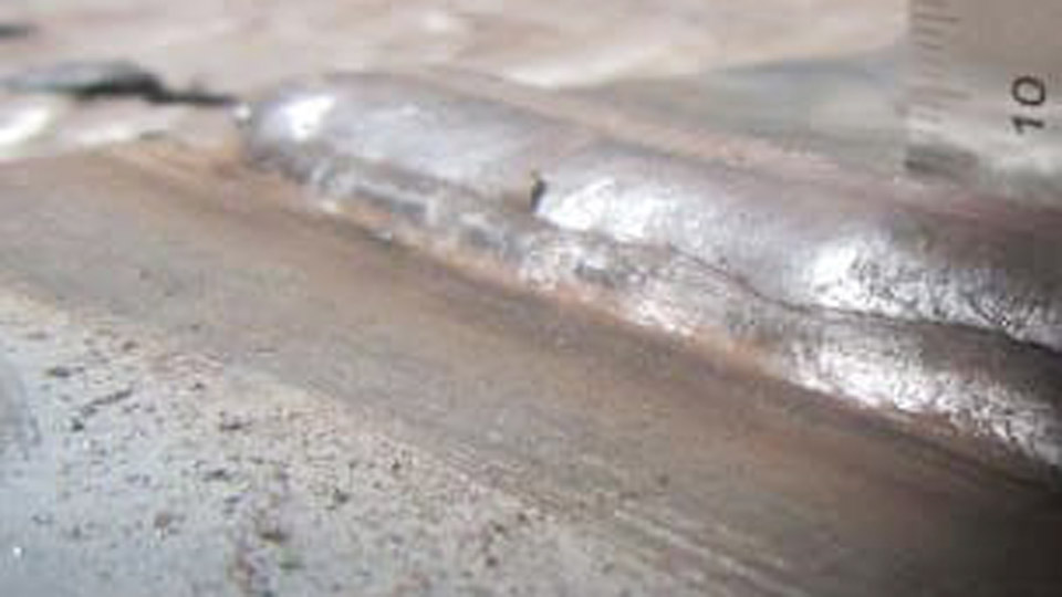
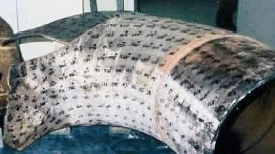
A finished weld looks solid until the inspector’s gage drops into a narrow groove along the toe and the part fails visual acceptance. That groove is undercut in welding defects—base metal melted by the arc and left unfilled by weld metal.
The notch reduces load-bearing cross-section and acts as a sharp stress riser that initiates fatigue cracks under cyclic loading long before the joint reaches its design life. Structural codes therefore treat undercut as a measured discontinuity with strict depth and length limits.
Knowing the exact parameter combinations that create it, the acceptance numbers that decide pass or reject, and the precise adjustments that eliminate it separates welds that survive inspection from those that require costly repair or rejection.
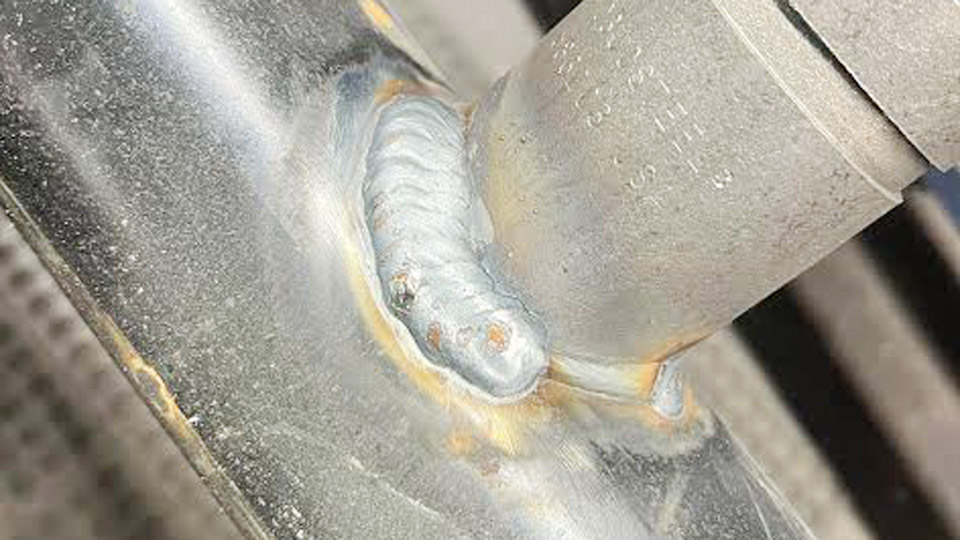
Image by r/Welding
Why Undercut Creates Immediate Structural Risk
Undercut is not merely cosmetic. The unfilled groove changes both the geometry and the stress distribution at the weld toe.
Stress Concentration Mechanics at the Weld Toe
The sharp radius at the bottom of an undercut multiplies local stress. Under tensile or bending loads the peak stress at the notch root can exceed the nominal stress by a factor of two or more.
In fatigue-sensitive members this elevation shortens crack-initiation life dramatically. Even shallow undercut oriented transverse to principal tensile stress becomes a preferred initiation site.
Static Capacity Loss Versus Fatigue Sensitivity
On statically loaded members the primary concern is reduced net section. On cyclically loaded members the notch effect dominates. Codes therefore apply tighter limits when the weld is transverse to computed tensile stress in primary members. The same depth of undercut that is tolerated on a compression flange is rejectable on a tension flange.
How Much Undercut Does AWS D1.1 Actually Allow?
Acceptance is governed by loading category, material thickness, and weld orientation. Limits are measured from the original base-metal surface to the deepest point of the groove.
Statically Loaded Nontubular Connections
For base metal thinner than 1 in (25 mm), maximum depth is 1/32 in (1 mm). An exception permits up to 1/16 in (2 mm) depth for an accumulated length of 2 in (50 mm) in any 12 in (300 mm) of weld on longer joints. On material 1 in and thicker the general limit rises to 1/16 in. Short welds carry a proportional length restriction for deeper undercut.
Cyclically Loaded Members and Primary Tension Locations
When the weld is transverse to computed tensile stress in primary members, depth is limited to 0.01 in (0.25 mm). All other locations remain at 1/32 in. These tighter numbers reflect the fatigue sensitivity of the notch.
Measurement Practice That Matches Code Language
Depth is measured with a bridge cam gage, V-WAC gage, or equivalent pit gage referenced to the original plate surface. Length of discontinuous undercut is accumulated along the weld. Smooth transition requirements still apply even when depth is within limits; a sharp step remains rejectable.
| Loading Condition | Material Thickness | Maximum Depth | Length Notes |
|---|---|---|---|
| Static, nontubular | < 1 in | 1/32 in | Up to 1/16 in for ≤ 2 in in 12 in |
| Static, nontubular | ≥ 1 in | 1/16 in | Any length |
| Cyclic, primary tension transverse | Any | 0.01 in | Strictest limit |
| Cyclic, all other | Any | 1/32 in | — |
ISO 5817 applies thickness-proportional limits (0.05t to 0.2t depending on quality level) with absolute caps of 0.5–2 mm, providing an alternative framework for projects written to European standards.
Parameter Combinations That Produce Undercut
Undercut forms when the arc melts more base metal at the toe than the weld pool can refill before solidification. Three variables dominate.
Excessive Current Relative to Travel Speed
High amperage widens the arc and increases the volume of melted base metal. If travel speed is also high, the pool freezes before filler metal can wet the melted groove. In SMAW this appears when 1/8 in E7018 is run above approximately 140–150 A on ¼ in plate while the operator advances too quickly.
In GMAW the equivalent is elevated wire-feed speed combined with travel rates above 10–12 ipm on thinner material.
Arc Length and Voltage Effects Across Processes
Long arc length (high voltage) spreads the arc cone, concentrating heat at the toes rather than in the joint center. The result is a wide, shallow undercut on both sides. Shortening the arc or dropping voltage 1–2 V narrows the dig and improves toe wetting without starving penetration.
Work Angle Errors on Fillet Welds
On a horizontal fillet the electrode or gun must bisect the joint angle so both legs receive equal heat. Tilting more than 10–15° toward the horizontal leg undercuts the vertical leg because gravity already pulls the pool downward.
The opposite tilt undercuts the horizontal plate. Maintaining a consistent 40–50° work angle on 2F fillets distributes energy evenly.
Process-Specific Undercut Risks and Corrections
Each process has characteristic failure modes that map directly to parameter or technique adjustments.
Stick Electrode Manipulation Issues
SMAW undercut is frequently caused by excessive amperage, long arc length, or failure to pause at the toes during a weave. Dropping current 5–10 A, holding arc length equal to core-wire diameter, and dwelling briefly at each toe allows filler to fill the melted edge.
On vertical-up 7018, current is already reduced; further reduction or a tighter weave eliminates residual undercut.
MIG Voltage and Wire-Feed Balance
In short-circuit GMAW, high voltage relative to wire-feed speed produces a fluid pool that pulls away from the toes. Reducing voltage while holding or slightly increasing wire speed restores the balance.
Spray-transfer regimes at high current require correspondingly higher travel speeds; if speed is not matched, undercut appears at the edges of the wide bead. Argon-rich mixtures (75/25 or 80/20 Ar/CO₂) wet better than pure CO₂ and reduce undercut tendency.
Flux-Cored High-Deposition Challenges
Self-shielded and gas-shielded FCAW run at high deposition rates. The combination of high current and fast travel readily creates undercut if the gun angle drifts or the operator fails to keep the arc aimed into the joint.
A slight drag angle and deliberate pause at the toes during any weave correct the imbalance. Contact-tip-to-work distance must remain consistent; excessive stick-out raises voltage and widens the arc.
Correcting Existing Undercut Without Compromising the Joint
Repair method depends on depth relative to code limits and the accessibility of the joint.
When Grinding Alone Is Sufficient
Undercut within or only slightly beyond acceptance limits is preferably blended by grinding to a smooth transition. Grinding removes the sharp notch without adding heat or residual stress from additional weld metal.
A pencil grinder or flap disc follows the contour until the original surface is restored and the transition radius is acceptable. On bridge or cyclic work the preference for grinding over weld repair is explicit in recent code editions.
When Additional Weld Metal Is Required
Deeper undercut that exceeds limits must be filled. First clean the groove of slag or scale, then deposit a small stringer or controlled weave sized to fill without excessive reinforcement.
The repair bead itself must meet the same acceptance criteria. Overfilling followed by grinding to profile is acceptable provided the final surface is free of new undercut or underfill.
Decision Sequence for Eliminating Undercut on the Next Weld
Begin with the governing code limits for the specific member and loading. Set current or wire-feed speed at the midpoint of the qualified range for the electrode or wire diameter and position. Establish travel speed that allows clear wetting of both toes.
Verify work angle places the arc force equally on both members of a fillet or centered in a groove. Maintain short, consistent arc length. After the first few inches, stop and gage the toes.
Adjust one variable at a time—usually current or travel speed first—until the groove disappears. Record the final combination for the WPS or shop traveler.
The difference between an acceptable toe and a rejectable notch is often only 5–10 A or a 10–15 % change in travel speed. Once the balance between melting rate and fill rate is locked, undercut ceases to appear.
Advanced operators further reduce risk on critical tension members by preferring stringer beads over wide weaves and by verifying interpass temperature so residual heat does not effectively raise the working amperage on subsequent passes.
FAQs
How much undercut is acceptable under AWS D1.1?
For statically loaded nontubular members thinner than 1 in the limit is 1/32 in depth (with limited length exceptions up to 1/16 in). Cyclically loaded primary tension members transverse to stress are limited to 0.01 in.
What causes undercut in welding most often?
Excessive current relative to travel speed, long arc length or high voltage, and incorrect work angle that concentrates heat on one toe.
Can undercut be repaired by grinding only?
Yes when depth is within or only marginally above code limits. Grinding to a smooth transition is preferred over adding weld metal on many cyclic and bridge applications.
Does travel speed or amperage matter more for undercut?
Both interact. High current melts more base metal; high travel speed prevents the pool from filling the melted groove before solidification. Adjusting either (or both) restores the balance.