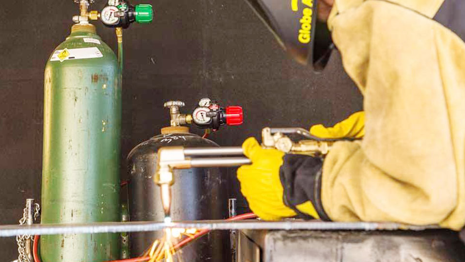
Undersized supply lines or incorrect tip pressure leave an oxy-natural gas torch with a soft, unstable flame that fails to preheat thick plate or produce a clean cut kerf.
The natural gas flow rate calculation formula converts appliance or tip BTU demand into cubic feet per hour (CFH), then sizes the orifice or pipe so the required volume arrives at the correct pressure.
Without that calculation, operators waste gas, experience flashbacks, or reject cuts because the oxygen-to-fuel ratio drifts.
Accurate flow prediction also determines whether a shop’s existing low-pressure utility line can support a multi-tip heating rose or a machine cutting station without installing a higher-pressure regulator.
The formulas that follow are the ones used by torch manufacturers, pipefitters, and code officials to keep heat input consistent and gas consumption predictable.

Image by meritusgas
Converting Equipment BTU Rating into Required Natural Gas Flow
Every heating tip, cutting tip, or rose is rated in British thermal units per hour. Natural gas supplies roughly 900–1,100 BTU per standard cubic foot; the industry standard conversion uses 1,000 BTU/scf.
Basic Volumetric Demand Equation
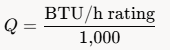
where is the required flow in CFH (or SCFH at standard conditions). A 150,000 BTU/h multi-flame heating tip therefore needs 150 CFH of natural gas. When the heating value of the local gas is known precisely (for example 1,050 BTU/scf), substitute that value in the denominator for a tighter estimate
Adjusting for Multiple Tips or Simultaneous Stations
Sum the individual tip demands, then apply a diversity factor only if the torches will never fire at full load together. For continuous machine cutting or heavy preheating, use 100 % of the summed rating. The resulting total CFH becomes the design flow for the pipe-sizing calculations that follow.
Orifice Flow Rate Formula for Tip and Mixer Jets
Most torch tips meter fuel gas through a fixed orifice. The low-pressure orifice equation predicts the volume that will pass at a given manifold pressure.
Standard Imperial Orifice Equation
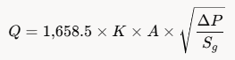
- = flow rate, CFH
- = discharge coefficient (0.85–0.95 for typical torch orifices; 0.90 is a practical average)
- = orifice area, in²
- = pressure drop across the orifice, inches water column
- = specific gravity of the gas (0.60 for typical natural gas)
Solving for Required Orifice Area
Rearrange to size a jet for a known flow and available pressure:
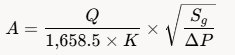
Example: a tip requiring 40 CFH at 7 in WC with and needs an orifice area of approximately 0.0075 in², corresponding to a drill size near #50. Manufacturers publish exact drill sizes, but the formula lets an operator verify that a worn or replaced orifice still delivers the design flow.
Metric Equivalent
When working in SI units the constant changes, but the square-root relationship between pressure and flow remains identical. Always convert local gauge pressure to the absolute differential used by the equation.
Low-Pressure Pipe Flow Formulas for Supply Lines
Utility natural-gas service is normally delivered at 7 in WC (approximately 0.25 psig). The allowable pressure drop from the meter to the torch is typically limited to 0.5 in WC by code. Two equations dominate low-pressure sizing.
Spitzglass Low-Pressure Equation
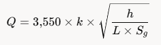
where
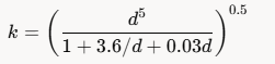
- = capacity, CFH
- = allowable pressure drop, inches water column
- = equivalent pipe length, ft (include fittings)
- = inside diameter, inches
- = 0.60
NFPA 54 / IFGC Equation
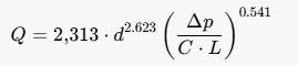
incorporates viscosity, density, and temperature corrections; for natural gas at 60 °F a typical value is approximately 0.6094 when pressures are expressed in inches water column. Both equations give conservative capacities for Schedule 40 steel and Type L copper. Always size for the longest run and the highest simultaneous demand.
Matching Calculated Flow to Actual Torch Tip Data
Manufacturer charts list measured SCFH for each tip size at recommended oxygen and fuel pressures. The calculation formulas above are used to confirm that the shop piping can deliver those chart values without excessive drop.
Typical Natural-Gas Preheat Flows for Cutting Tips
For a two-piece natural-gas cutting tip cutting 1 in plate, preheat natural-gas consumption commonly falls in the 35–45 CFH range at 5–8 psig fuel pressure. Heavier plate or multi-flame heating roses climb to 100–250 CFH. Oxygen flow is usually 1.5–2 times the natural-gas volume for a neutral-to-slightly-oxidizing flame.
Verifying Supply Capacity Against Tip Demand
Calculate the required CFH from the tip chart, add 10–15 % for hose and fitting losses, then run the Spitzglass or NFPA equation for the proposed pipe diameter and length.
If the calculated capacity is less than the adjusted demand, increase pipe size or raise delivery pressure with a second-stage regulator.
Influence of Specific Gravity, Temperature, and Pressure on Real Flow
Natural-gas composition varies by region; specific gravity can range from 0.55 to 0.70. Higher specific gravity reduces flow through the same orifice by the square-root relationship shown in the orifice equation. Temperature affects both density and viscosity; most tables assume 60 °F.
For outdoor winter operation the gas is denser, so measured CFH at the torch will be lower than the nameplate value unless the regulator is adjusted.
Absolute versus Gauge Pressure
All orifice and pipe equations use the pressure differential that actually drives flow. A regulator set at 7 in WC gauge produces a differential of 7 in WC only if the downstream pressure is atmospheric. Downstream restriction (long hose, small tip) reduces the effective (\Delta P) and therefore the delivered volume.
Practical Calculation Sequence for a New Heating or Cutting Station
- Obtain the manufacturer’s BTU/h or SCFH rating for every tip that will operate simultaneously.
- Convert BTU ratings to CFH using the 1,000 BTU/scf rule (or the local heating value).
- Add hose and fitting equivalent lengths to the measured pipe run.
- Select an allowable pressure drop (commonly 0.3–0.5 in WC for low-pressure systems).
- Solve the Spitzglass or NFPA equation for the smallest pipe diameter that meets or exceeds the total CFH.
- Confirm the tip orifice itself can pass the required flow at the available manifold pressure using the orifice equation.
- Install a flow meter or clock the gas meter under load to verify the calculated values match field conditions.
Advanced Insight: Compensating for Long Hose Runs and Flashback Arrestors
Each flashback arrestor and every 25 ft of ¼-in hose adds measurable pressure drop. On high-flow natural-gas heating tips the cumulative restriction can drop fuel pressure below the 4–5 oz/in² minimum required for stable mixing.
The practical correction is to increase regulator delivery pressure 2–3 psig for every additional 25 ft of hose or to step up to ⅜-in hose once tip size exceeds No. 5.
Recalculate the orifice flow with the new upstream pressure; the square-root relationship shows that doubling absolute differential pressure increases flow by only 41 %, so hose diameter changes are usually more effective than pressure increases alone.
Correct application of the natural gas flow rate calculation formula—whether the simple BTU-to-CFH conversion, the orifice equation, or the Spitzglass pipe-sizing formula—guarantees that the volume arriving at the torch matches the tip chart.
When the calculated supply capacity equals or exceeds tip demand at the design pressure drop, flame stability, cut quality, and gas economy remain consistent across the full range of plate thicknesses.
FAQs
What is the simplest natural gas flow rate calculation formula for a heating tip?
Divide the tip’s BTU/h rating by 1,000. A 200,000 BTU/h rose therefore requires approximately 200 CFH of natural gas.
How do I calculate natural gas flow through a torch orifice?
Use . With , , and pressure in inches water column, the result is CFH.
Which pipe-sizing formula is used for low-pressure natural gas to a welding shop?
The Spitzglass low-pressure equation or the NFPA 54 equation both give reliable CFH capacity for pressures under 1.5 psig and pressure drops of 0.5 in WC or less.
Does natural gas specific gravity change the required flow rate calculation?
Yes. Higher specific gravity reduces volume flow through a fixed orifice by the square root of the gravity ratio; always insert the local value into the orifice or pipe equation.