Every pipe welder has faced the same frustrating scenario: midway through a multi-joint run on schedule 40 carbon steel, you run short on 1/8-inch E7018 electrodes or .035-inch ER70S-6 wire. Over-ordering wastes money and inventory space; under-ordering kills productivity and risks rushed, lower-quality repairs.
A pipe welding consumable calculator solves this by delivering precise estimates of electrodes, filler wire, flux, and even shielding gas based on pipe diameter, wall thickness, joint geometry, welding process, and real deposition efficiencies.
This tool turns guesswork into data-driven planning. It helps DIY hobbyists, students, and professionals avoid costly shortages while controlling material budgets on everything from small shop fabrications to field pipeline repairs.
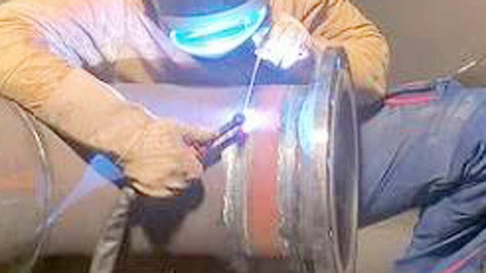
Image by welderdestiny
Understanding Weld Metal Volume in Pipe Joints
Core Geometry Factors for Accurate Calculations
Pipe welding consumable needs start with the cross-sectional area of the weld groove or fillet. For girth (circumferential) butt welds—the most common in piping—calculate the weld length as the pipe circumference: π × outside diameter (OD).
Key inputs include:
- Wall thickness (t)
- Bevel angle (typically 30° per side for a 60° included angle)
- Root gap (usually 1.5–3 mm)
- Root face/land (1–2 mm)
- Reinforcement height (1–3 mm on cap and root)
The basic approach breaks the groove into triangles for bevels, a rectangle for the root gap, and an additional cap area. Multiply the total cross-sectional area by the circumference (and number of passes if multi-layer) to get volume.
Density and Unit Conversions
Steel weld metal density is consistently 7.85 g/cm³ (or 0.283 lb/in³). Convert all dimensions to consistent units—centimeters for metric ease or inches for imperial. Volume (cm³) × density gives deposited weld metal weight in grams (divide by 1000 for kg). This deposited weight forms the foundation before applying process-specific losses.
For a quick 6-inch Schedule 40 pipe (OD ≈ 168.3 mm, t ≈ 7.1 mm) single-V girth weld with standard 60° bevel, 2 mm root gap, and 2 mm reinforcement, the deposited metal per joint often falls in the 0.35–0.55 kg range before efficiency adjustments.
Advanced Pipe Welding Calculator
Deposition Efficiency Across Welding Processes
SMAW (Stick) Electrode Efficiency
Shielded Metal Arc Welding (SMAW) is the go-to for field pipe work due to its portability. Typical deposition efficiency ranges 55–70%:
- E6010/E6011 (cellulosic): 50–58% due to higher spatter and stub loss
- E7018 (low-hydrogen): 65–72% with iron powder coatings improving recovery
Stub loss (≈2 inches per 14-inch rod) and slag account for much of the remainder. A pipe welding consumable calculator multiplies deposited weight by roughly 1.4–1.8 for SMAW electrodes.
GMAW/FCAW Wire Processes
Gas Metal Arc Welding (GMAW/MIG) and Flux-Cored Arc Welding (FCAW) achieve higher efficiencies:
- Solid wire (ER70S-6): 92–98%
- Flux-cored: 80–90%
These processes waste less to spatter, especially with spray transfer or pulsed modes. For the same 6-inch joint, you might need only 0.4–0.6 kg of wire versus 1.0+ kg of stick electrodes.
GTAW and SAW Considerations
Gas Tungsten Arc Welding (GTAW/TIG) offers near 95–100% efficiency for root passes on critical stainless or alloy pipes but is slower. Submerged Arc Welding (SAW) for larger-diameter shop fabrication approaches 99% for wire but requires separate flux calculations (typically 1.0–1.7 × wire weight).
Step-by-Step Pipe Welding Consumable Calculation
Example: 8-Inch Schedule 40 Carbon Steel Girth Weld (SMAW)
- Gather specs: OD = 219.1 mm, t = 8.18 mm, 60° single-V, 2 mm root gap, 2 mm reinforcement, full circumference.
- Approximate groove area: Use formulas or break into shapes—bevel triangles + root rectangle + cap. Typical area ≈ 0.8–1.2 cm² for this thickness.
- Volume: Area × circumference (≈ 68.8 cm).
- Deposited weight: Volume × 7.85 g/cm³ ≈ 0.5–0.7 kg.
- Consumable required: Divide by efficiency (0.65 for E7018) → ≈ 0.8–1.1 kg electrodes. Add 10–15% contingency for field variables.
This equates to roughly 10–15 pounds of 1/8-inch rods for multiple joints, depending on exact geometry.
Multi-Pass and Position Adjustments
Root passes (often E6010) consume differently than fill/cap (E7018). Vertical and overhead positions increase spatter and require slightly more material. Calculators factor these by adjusting efficiency downward 5–10% for out-of-position work.
Process-Specific Consumable Selection for Pipes
SMAW Electrodes for Different Materials and Thicknesses
Carbon Steel:
- Root: E6010 (3/32–1/8 inch, 70–125 A) for deep penetration
- Fill/Cap: E7018 (1/8–5/32 inch, 90–180 A) for low-hydrogen control
Stainless Steel Pipes:
- ER308L or E308-16 equivalents. Lower travel speeds and tighter heat input increase relative consumption but demand precise matching for corrosion resistance.
Alloy and High-Strength Pipes (e.g., X70 pipeline):
- E8018-G or similar. Preheat and interpass controls affect total usage through more controlled, sometimes slower deposition.
| Pipe NPS | Schedule | Wall (in) | Approx. E7018 per Girth Weld (kg) | Notes |
|---|---|---|---|---|
| 4″ | 40 | 0.237 | 0.8–1.2 | Standard V |
| 6″ | 40 | 0.280 | 1.4–2.0 | Multi-pass |
| 8″ | 40 | 0.322 | 2.0–2.8 | Field typical |
| 12″ | 40 | 0.406 | 3.6–4.8 | Higher volume |
MIG/FCAW Wire Diameters and Parameters
0.035-inch wire is versatile for most pipe walls. Wire feed speed (WFS) directly ties to deposition rate—e.g., 300–400 ipm for .035-inch at 150–250 A. Higher WFS reduces total time but requires stable parameters to maintain efficiency.
Advanced Factors Influencing Calculator Accuracy
Joint Design Variations
- Double-V grooves: Reduce volume for thick walls (>20 mm) by welding from both sides.
- Socket welds: Treated as fillets; leg size drives calculation (volume ≈ 0.5 × leg² × circumference).
- Branch connections: More complex—use reinforcement pads or specialized formulas accounting for intersecting cylinders.
Wider bevel angles or larger root gaps dramatically increase volume. A 70° vs. 60° included angle can add 15–20% more filler.
Material and Environmental Variables
Stainless densities (≈7.9–8.0 g/cm³) and nickel alloys (higher) shift weight calculations. Field conditions—wind, humidity, pipe fit-up quality—affect real-world efficiency more than shop settings. Track actual consumption on the first few joints and refine inputs.
Shielding Gas and Flux Estimates
For GMAW: Gas flow (15–25 CFH) × arc time. Calculators often include this based on deposition rate. SAW flux consumption is typically 1–1.7 kg per kg wire.
Integrating a Pipe Welding Consumable Calculator into Workflow
Input pipe specs, joint type, process, and number of welds. Output includes total kg/lbs, rod counts (accounting for standard lengths), wire spool estimates, and contingency. Many free or app-based versions reference AWS and ASME data for credibility.
For long runs, scale by linear footage or joint count. Always validate with a test coupon matching the exact material and position.
Real-World Decision Making with Calculated Data
Choose processes balancing speed, quality, and cost. SMAW excels in field accessibility but consumes more per joint. MIG/FCAW shines in shops for higher productivity and lower material use. For critical piping (ASME B31.3, API 1104), precise calculations support WPS qualification and cost bidding.
Monitor actual vs. calculated usage to improve future estimates and identify technique issues like overwelding.
Wrapping Up
Effective pipe welding consumable planning combines geometric precision, process knowledge, and field validation. By mastering these calculations, welders make informed choices on material orders, process selection, and parameter optimization that directly improve joint quality, project timelines, and profitability.
The next level comes from integrating these numbers into broader WPS development and cost tracking—turning a simple calculator into a competitive edge on every pipe project.
FAQ
How do I calculate electrode needs for a long pipeline run?
Measure total weld length (joints × circumference), determine average cross-section per joint, compute deposited weight, then apply process efficiency and 10–15% buffer. For SMAW on carbon steel, expect 10–25 kg electrodes per ton of fabricated pipe depending on diameters and schedules.
Does pipe position significantly affect consumable usage?
Yes. Overhead and vertical-up welding often increase spatter and require more passes or wider beads, lowering effective deposition efficiency by 5–15%. Adjust calculator inputs accordingly or use position-specific efficiency factors.
What’s the best way to estimate for stainless pipe welding?
Use the same volume formulas but apply stainless density (≈7.9 g/cm³) and match filler (e.g., ER308L). GTAW roots + SMAW or FCAW fills are common; TIG offers higher efficiency but slower overall consumption per hour.
How accurate are online pipe welding consumable calculators?
They provide strong starting estimates when based on AWS geometry and verified efficiencies. For production, cross-check with test welds and historical job data. Add project-specific contingencies for fit-up variations and welder technique.