Brazing HVAC copper lines requires precise heat control, proper joint preparation, and the correct filler metal to create strong, leak-resistant connections. Learning how to braze HVAC copper lines is essential when installing refrigerant piping, repairing damaged connections, or replacing system components.
Excessive heat can oxidize the inside of the tubing, damage nearby valves, and affect joint quality, while insufficient heating can prevent the filler metal from flowing properly through the joint. These problems may lead to refrigerant leaks, costly callbacks, and reduced system reliability.
Proper brazing technique involves cleaning and fitting the copper, selecting a suitable torch and filler rod, flowing dry nitrogen through the tubing when required, and heating the joint evenly.
Understanding these factors helps HVAC technicians and apprentices produce reliable copper joints while reducing contamination, rework, and the risk of premature connection failure.
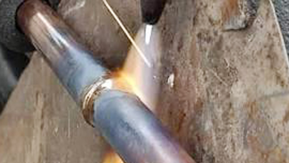
Image by fb/Andrii Bog
Why Nitrogen Flow Rate Controls Internal Oxide Formation
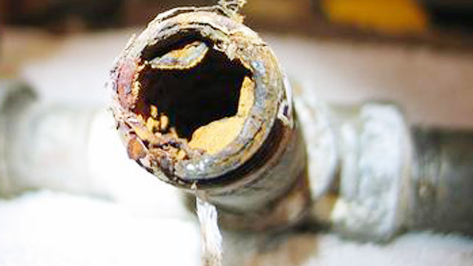
Copper reaches brazing temperature above 1,100 °F. At that heat any oxygen remaining inside the tube reacts almost instantly to form cupric oxide. The scale adheres loosely and later circulates through the system.
Setting the Correct SCFH and Pressure
Industry practice settles on a continuous low-volume flow of dry nitrogen at 2–5 SCFH, most commonly 2–3 SCFH. Regulator delivery pressure is typically 1.5–2 psi. The exit stream should feel like a faint whisper against the hand or cheek—strong enough to displace oxygen, weak enough that it does not cool the joint or force molten alloy out of the capillary gap.
When to Start and Stop the Purge
Begin nitrogen flow before the torch flame touches the copper. Maintain the flow through the entire heating and cooling cycle until the joint is cool enough that oxygen can no longer react. Cutting the purge while the metal is still hot allows fresh oxygen to re-enter and form scale on the inner surface.
Connection Points and Exit Path
Remove Schrader cores so flow is unrestricted. Introduce nitrogen at one service port or open end and leave a clear exit path at the opposite end or another port. Never allow pressure to build inside the tubing; excess pressure interferes with filler penetration.
Selecting Brazing Alloy by Joint Type and Clearance
Alloy chemistry determines melting range, fluidity, and whether separate flux is required.
Copper-to-Copper Joints
BCuP alloys are standard. Phosphorus provides self-fluxing action on clean copper, eliminating the need for external flux paste. BCuP-5 (15 % silver, commonly sold as Stay-Silv 15 or Sil-Fos 15) offers the best balance of flow, ductility, and gap-filling ability for residential and light-commercial line sets.
Solidus is approximately 1,190 °F; liquidus is approximately 1,475 °F. Working range sits near 1,300–1,500 °F. Lower-silver grades such as BCuP-2 or BCuP-3 cost less but demand tighter joint clearances and produce less ductile results under vibration.
Copper-to-Brass or Dissimilar Metal Joints
BCuP alloys are not recommended for brass, steel, or nickel-bearing metals. Switch to a silver-based BAg alloy and apply the appropriate flux. Flux removes oxides from the non-copper surface and promotes wetting. Choose the silver content according to the metals involved and the manufacturer’s joint-design data.
Joint Clearance Requirements
Target capillary clearance of roughly 0.002–0.005 inch. Excessively tight fits restrict alloy flow; loose fits allow the molten filler to run out before the joint is filled. Swaged or factory fittings that maintain this range produce consistent results.
Torch Selection and Flame Characteristics for Even Heat
Oxy-acetylene remains the most controllable heat source for precise HVAC work. Air-acetylene and oxy-MAP systems are usable on smaller tubing but deliver less concentrated heat.
Regulator Pressures and Tip Size
Pressures vary with tip orifice and tube diameter. Typical starting points for ¼–½ inch copper are 4–7 psi acetylene and 8–12 psi oxygen. Larger tubing or rosebud tips require higher settings.
Always adjust with the torch valves open so the delivered pressure matches actual flow. Select the smallest tip that still heats the joint evenly; oversized tips waste gas and increase the risk of overheating.
Neutral versus Slightly Carburizing Flame
A neutral flame (sharp inner cone, no secondary feather) or a slightly carburizing flame (small secondary feather) protects the copper surface. An oxidizing flame (harsh, hissing, short cone) accelerates surface oxidation and weakens the joint.
Color of the copper itself is the practical indicator: dark cherry to cherry red signals the correct temperature window for most BCuP alloys.
Surface Preparation That Enables Capillary Action
Filler metal will not wet contaminated or oxidized surfaces reliably.
Cleaning Sequence
Cut the tube square with a tubing cutter. Ream the inside to remove the burr that would otherwise restrict flow or create turbulence. Clean the outside of the tube end and the inside of the fitting cup with abrasive cloth or a dedicated copper brush until bright metal appears.
Wipe away residual particles and any residual oil or moisture. Do not touch the cleaned surfaces with bare hands after preparation.
Fit-Up and Support
Insert the tube fully into the fitting cup. Support the assembly so the joint cannot shift while the alloy is molten. Any movement after the filler solidifies can open microscopic paths for later leakage.
Heating Sequence That Draws Alloy by Capillary Force
The base metal—not the filler rod—must reach brazing temperature.
Even Circumferential Heating
Direct the flame primarily at the tube first, then move to the fitting, keeping the torch in continuous motion. Heat both sides of the joint so temperature equalizes around the circumference. When the copper reaches dark cherry red, touch the filler rod to the joint opposite the flame.
Capillary action pulls the alloy into the gap. Feed only enough rod to form a continuous fillet; excess alloy does not increase strength and can obstruct internal flow.
Avoiding Direct Rod Melting
Never melt the rod in the flame and drip it onto a cold joint. The alloy must be drawn by the heat of the base metals. If the rod balls up or fails to wet, either the surface is dirty or the joint temperature is still too low.
Protecting Heat-Sensitive Components During the Braze
Service valves, TXV bulbs, and nearby insulation cannot tolerate brazing temperatures.
Heat Sinks and Barriers
Wrap valves, sensors, and adjacent tubing with wet rags or commercial heat-blocking putty. Keep the wet material in contact until the joint cools. Position the torch so the flame envelope stays away from these components.
When brazing near a compressor or indoor coil, sequence the joints so the nitrogen path and heat path do not concentrate thermal load on sensitive parts.
Post-Braze Verification and System Integrity Checks
A visually acceptable fillet is not proof of a sealed joint.
Cooling Under Nitrogen
Continue the low-flow nitrogen purge until the copper is cool to the touch. This prevents oxygen from contacting the still-hot inner surface and forming additional scale.
Nitrogen Pressure Test
After cooling, pressurize the completed line set with dry nitrogen to a value well above operating pressure—commonly 150–300 psi or the manufacturer’s specified test pressure. Hold the pressure for 10–15 minutes and watch for gauge drop. Any measurable loss requires locating and repairing the leak before evacuation.
Evacuation Readiness
Only after a successful pressure test proceed to deep vacuum. Residual moisture or non-condensables left by incomplete purging or poor technique will show up as elevated micron readings and extended pump-down times.
Final Thoughts
Successful brazing of HVAC copper lines rests on four controlled variables: continuous low-flow nitrogen that keeps oxygen out, alloy matched to the metals and clearance, even heating that lets capillary action fill the joint, and verification that the finished assembly holds pressure.
When these decisions align, the joint survives vibration, thermal cycling, and high-pressure refrigerants without introducing scale or leaks into the circuit.
Advanced operators further refine results by sequencing joints from the nitrogen inlet outward and by matching tip size and flame energy precisely to tube diameter, minimizing both total heat input and the time the copper spends at elevated temperature.