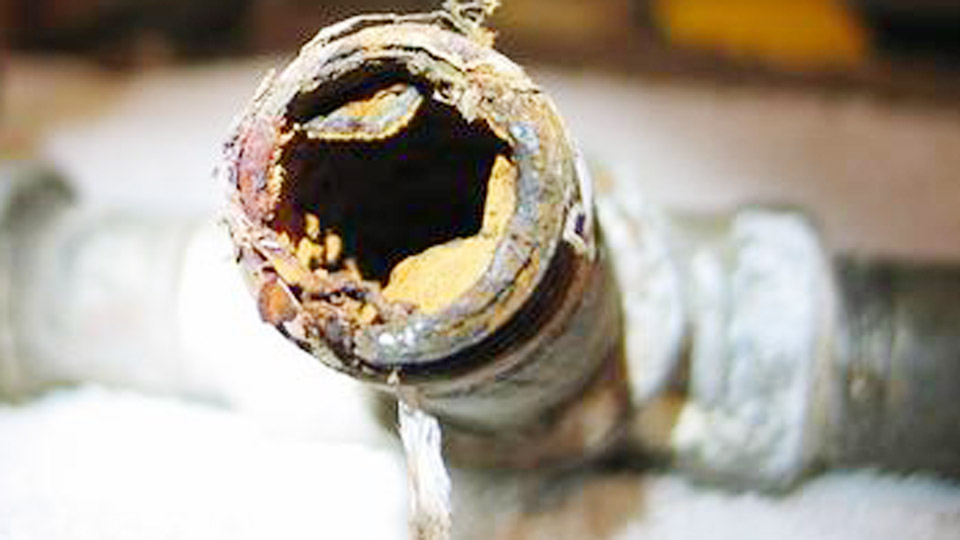
Brass joints fail when zinc boils out of the puddle, leaving porosity, undercut, or brittle deposits that crack under load. Learning how to weld brass with TIG and MIG welding solves that by matching polarity, heat input, and zinc-free fillers to the alloy’s high conductivity and low zinc boiling point.
Incorrect settings produce white oxide clouds, contaminated tungsten, or weak fusion that no amount of grinding fixes later.
The right combination of silicon bronze or aluminum bronze filler, controlled amperage, pure argon shielding, and deliberate travel speed keeps zinc vaporization manageable while achieving full fusion on both thin sheet and heavier plate.
This guide delivers the exact parameter windows and decision points needed for clean, serviceable brass welds.
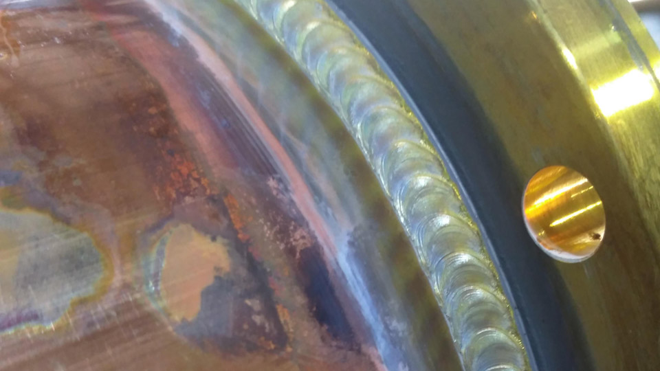
Image by r/Welding
Why Brass Requires Controlled Heat and Zinc-Free Filler
Brass is a copper-zinc alloy whose weldability drops sharply as zinc content rises. Zinc boils near 907 °C, well below the melting range of most copper alloys, so the arc drives rapid vaporization that creates gas pockets and oxide films.
Zinc Vaporization and Resulting Defects
High-zinc brasses generate more white smoke and leave more porosity than low-zinc grades. The vapor also contaminates the tungsten on TIG or interferes with arc stability on MIG.
Using a zinc-free filler such as ERCuSi-A reduces the total zinc available in the puddle and lets silicon form a protective surface film that limits further evaporation.
Thermal Conductivity and Heat-Input Limits
Copper alloys pull heat away from the joint faster than steel. This forces higher amperage or preheat on thicker sections, yet excess heat accelerates zinc loss and softens the surrounding metal.
The practical response is pulsed current on TIG or short-circuit transfer with rapid travel on MIG, keeping total energy input just high enough for fusion.
Filler Metal Choices That Determine Joint Integrity
Filler selection overrides nearly every other variable once the joint is clean.
Silicon Bronze (ERCuSi-A) as the Primary Option
ERCuSi-A contains roughly 3 % silicon and almost no zinc. It melts lower than the base metal, flows readily, and produces deposits in the 50–60 ksi range with good corrosion resistance.
Diameter is matched or one size smaller than material thickness—1.6 mm rod for 2 mm sheet, 2.4 mm for 3 mm plate. The silicon deoxidizes the puddle and suppresses zinc fuming better than most alternatives.
Aluminum Bronze and Specialty Fillers
ERCuAl-A2 supplies higher strength (often above 70 ksi) and a closer yellow color match on some alloys. It demands slightly higher amperage and a more deliberate technique because the puddle is less fluid.
Phosphor bronze (ERCuSn-A) appears in limited color-critical work but is less common for structural joints. Never feed zinc-bearing brass rod into the arc; the additional zinc increases porosity and fume without improving properties.
TIG Welding Brass – Current, Amperage, and Technique Decisions
TIG remains the preferred process for sheet, fittings, and appearance-critical work because the operator controls heat input continuously with a foot pedal.
DCEN versus AC Current Selection
DCEN concentrates heat in the workpiece and produces a stable, quiet arc with a pointed 2 % lanthanated or ceriated tungsten. Most production procedures use DCEN.
AC supplies a cleaning action that can help on heavily oxidized surfaces, but the electrode positive portion increases zinc vaporization and widens the heat-affected zone. When AC is required, set balance toward 70–80 % electrode negative and use a slightly rounded tip.
Amperage Windows by Thickness
| Thickness | DCEN Amperage | Tungsten Diameter | Typical Cup / Notes |
|---|---|---|---|
| 0.8–1.5 mm | 30–70 A | 1.6 mm | #7 cup, pedal average 40–50 A |
| 1.5–3.0 mm | 70–130 A | 2.4 mm | #8 cup + gas lens, 1–2 PPS pulse |
| >3 mm | 130 A+ | 3.2 mm | #10 cup + gas lens, optional preheat |
Stay in the lower half of each range during welding; raise current only when the puddle fails to wet. Pure argon at 15–20 CFH covers most work; add 25 % helium only when penetration on thick sections is insufficient at maximum machine output.
Torch Angle, Arc Length, and Filler Technique
Hold a 10–15° push angle and keep arc length roughly equal to tungsten diameter. Form the puddle first, then dip the silicon-bronze rod into the leading edge once every 1–2 seconds.
A long arc spreads heat and invites porosity; a short arc with rhythmic filler addition keeps zinc vapor moving out of the pool. For multi-pass joints, allow interpass cooling and clean thoroughly between layers.
MIG Welding Brass – Wire Feed, Gas, and Parameter Windows
MIG deposits metal faster and suits thicker sections or production runs where TIG speed is limiting.
Shielding Gas and Metal-Transfer Mode
Pure argon at 20–25 CFH is the most consistent choice; it stabilizes the arc and reduces zinc fuming compared with argon-CO₂ mixes.
Short-circuit or controlled short-circuit transfer keeps heat input low. Spray transfer is usable only on heavier plate with higher voltage and risks excessive zinc loss.
Voltage, Wire Speed, and Stick-Out Starting Points
| Thickness | Wire Diameter | Voltage | Wire Speed (ipm) | Approximate Amperage |
|---|---|---|---|---|
| 1/16 in | 0.030 in | 17–19 V | 180–250 | 60–100 A |
| 3/32 in | 0.030 in | 18–20 V | 220–300 | 80–130 A |
| 1/8 in | 0.030–0.035 in | 19–22 V | 250–350 | 100–160 A |
| 3/16 in | 0.035 in | 20–23 V | 300–400 | 140–190 A |
Polarity is DCEP. Maintain ⅜–½ in stick-out and a 10–15° push angle. Travel fast enough that the puddle wets without racing ahead; if porosity appears, shorten the arc and increase travel speed rather than raising voltage.
Joint Preparation and Heat-Management Controls
Surface condition and temperature control determine whether the selected parameters succeed.
Cleaning and Edge Preparation Requirements
Remove oils, oxides, and mill scale with a stainless-steel brush dedicated to copper alloys or by light grinding followed by solvent wipe.
For butt joints thicker than 1.5 mm, prepare a 60–70° included angle so the lower-melting filler can wet the root. Backing bars of copper or aluminum help dissipate heat on thin sheet and prevent burn-through.
Preheat and Interpass Temperature Limits
Thin brass rarely needs preheat. Sections above 6 mm benefit from 100–250 °C preheat to reduce the thermal gradient and the amperage required for fusion.
Keep interpass temperature low enough that the next pass does not overheat the previous deposit; excessive heat softens the brass and promotes cracking on cooling. Slow cooling under insulation after the final pass reduces residual stress in restrained joints.
Selecting TIG or MIG for Specific Brass Applications
TIG is the default for material under 3 mm, decorative work, or any joint where appearance and precise heat control matter. MIG becomes the practical choice once thickness exceeds 3–4 mm or when deposition rate and production speed take priority.
On mixed-thickness assemblies, TIG the thin sections and switch to MIG for the heavier members after verifying filler compatibility. In all cases the zinc-free silicon-bronze or aluminum-bronze filler remains constant; only the process parameters change.
Wrapping Up
When the puddle shows minimal white smoke, the toes wet cleanly without undercut, and the slag or surface oxide lifts easily, the combination of polarity, current, gas, and filler is correct for that alloy and thickness.
Advanced operators further reduce heat input by combining low-frequency pulse on TIG or programmed short-circuit transfer on MIG with deliberate stitch sequencing on highly restrained joints, preserving both mechanical properties and dimensional stability.