A cold solder joint is one of the most common causes of unreliable electrical connections, yet it can be difficult to identify until a circuit begins to fail. Formed when solder does not reach the proper melting temperature or the joint is disturbed before it solidifies, a cold solder joint creates a weak mechanical bond and poor electrical conductivity.
The result can be intermittent connections, increased resistance, overheating, or complete circuit failure in everything from consumer electronics to automotive wiring.
Recognizing the signs of a cold solder joint and understanding why it occurs are essential for producing durable, high-quality soldered connections.
With the right inspection methods and soldering techniques, you can prevent this defect, improve joint reliability, and ensure long-lasting electrical performance.
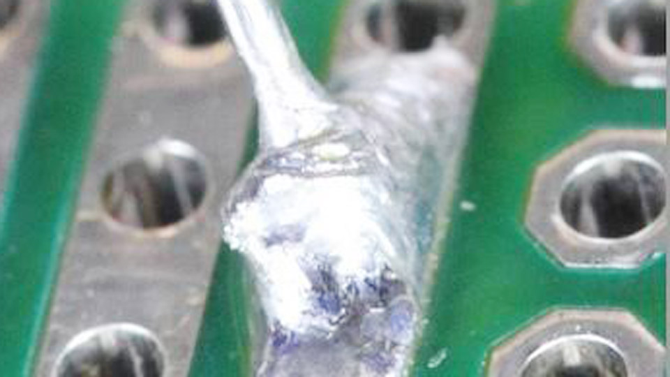
Image by pcbdirectory
Metallurgical Failure Mode Inside a Cold Solder Joint
Incomplete Wetting and Missing Intermetallic Layer
A proper solder joint requires the molten alloy to wet both the component lead and the copper pad, then form a thin intermetallic compound (IMC) layer—typically Cu6Sn5 on copper. In a cold solder joint the alloy never fully transitions from solid to liquid across the entire interface.
Surface oxides remain, flux activity is incomplete, and atomic diffusion cannot create a continuous IMC. The solder sits on top of the pad rather than bonding with it. Cross-section microscopy shows voids or a sharp boundary instead of the normal intermetallic scallops.
Grain Structure and Mechanical Brittleness
When solder solidifies from a fully liquid state it forms equiaxed grains with a bright, reflective surface (especially SnPb alloys). A cold joint freezes while still pasty. The resulting structure is coarse, dendritic, and often contains unmelted particles.
This microstructure has low ductility; cyclic stress opens micro-cracks that propagate until the joint opens electrically. Lead-free SAC alloys exaggerate the problem because their higher liquidus and narrower pasty range leave less margin for error.
Electrical Resistance Path
Even a joint that initially conducts can develop resistance of several ohms once micro-cracks form. In signal circuits this appears as intermittent drop-outs; in power circuits it generates localized heating that accelerates further degradation. Continuity meters frequently miss the defect because probe pressure can temporarily close the gap.
Visual and Electrical Indicators That Confirm the Defect
Surface Appearance Under Magnification
A good joint shows a smooth, concave fillet that feathers onto the pad with a contact angle under 40°. A cold solder joint is typically dull, grainy, or frosted. Edges are abrupt; the solder may form a ball or pillow rather than a fillet. Cracks or a visible ring around the lead are common.
Under 10–20× magnification the surface looks crystalline rather than glassy. Lead-free joints can appear dull even when good, so texture and fillet geometry become the decisive criteria.
Continuity and Thermal Behavior
Apply a gentle mechanical stress—light flex of the board or tug on the lead—while monitoring resistance. A cold joint often shows resistance that jumps or opens under load. Thermal imaging or a simple touch test can reveal a joint that runs hotter than its neighbors under the same current.
In through-hole work the solder may fail to wick fully up the barrel, leaving a concave meniscus on the secondary side.
Distinguishing Related Defects
A disturbed joint (moved during solidification) shows a shifted or fractured surface but may still have wetted properly. A dry joint results from contamination even when heat was adequate. Cold joints are defined by insufficient peak temperature or dwell; the visual and electrical signatures overlap but the root cause and corrective action differ.
Primary Process Variables That Create Cold Solder Joints
Tip Temperature Relative to Alloy Liquidus
Sn63/Pb37 melts at 183 °C; typical iron tip temperature is 320–350 °C to overcome thermal mass. SAC305 liquidus is approximately 217–220 °C; tip temperatures of 350–380 °C are common. If the tip is set too low or has oxidized and lost heat-transfer efficiency, the joint never reaches liquidus.
Large ground planes act as heat sinks, dropping local temperature 30–50 °C below the tip reading within seconds.
Dwell Time and Heat Transfer Path
Even at correct temperature, heat must flow through the lead and pad long enough for flux activation and wetting—typically 2–4 seconds for small SMD pads, 4–8 seconds for through-hole or heavy copper. Short contact leaves the interface below liquidus. Excessive time risks pad lift or component damage, so the window is narrow.
Surface Condition and Flux Activity
Oxides, oils, or residual flux residues raise the energy barrier for wetting. Flux must remain active at the peak temperature long enough to clear oxides. Rosin-core solder or liquid flux applied just before heat is essential. Old or contaminated solder wire itself can introduce oxides that the flux cannot fully reduce.
Movement During the Pasty Range
Any relative motion between lead and pad while the alloy is between solidus and liquidus freezes in residual stress and creates a fractured microstructure identical in appearance to a cold joint. Fixturing or simply holding the iron steady until the joint solidifies prevents this secondary failure mode.
Corrective Actions Once a Cold Joint Is Identified
Controlled Reflow Procedure
Clean the joint of residual flux and debris. Apply fresh flux. Heat the pad and lead simultaneously with a clean, properly tinned tip until the existing solder becomes fully liquid and the fillet reforms. Add a small amount of new solder if volume is insufficient.
Withdraw the iron and allow the joint to solidify without movement. For multi-lead components sequential reflow of adjacent pins can avoid thermal shock.
When Replacement Is Required
If the pad has lifted or the lead is damaged, the joint cannot be salvaged by reflow alone. Cut the lead, clear the via or pad, and install a new component or use a wire jumper. Attempting repeated reflows on a compromised pad risks further delamination.
Verification After Repair
Inspect under magnification for a smooth concave fillet. Perform a continuity check under light mechanical stress. For critical circuits, thermal cycle the assembly and re-test. Document the location so process controls can be adjusted upstream.
Process Controls That Eliminate Cold Joints at the Source
Iron Tip Selection and Maintenance
Match tip geometry to the joint: chisel or bevel for through-hole, fine conical or hoof for SMD. Keep the tip tinned and free of oxide. A tip that fails to transfer heat will produce cold joints regardless of set-point. Temperature-controlled stations with closed-loop feedback are preferred over uncontrolled irons.
Thermal Profile Discipline
For hand soldering, develop a consistent sequence: flux, position, heat pad and lead together, apply solder to the joint (not the tip), hold until wetting occurs, then remove heat.
For reflow ovens, ensure the time-above-liquidus (TAL) meets the alloy specification—typically 60–90 seconds for SAC305—and that peak temperature is reached uniformly across high-thermal-mass areas.
Board and Component Preparation
Clean pads and leads before soldering. Use thermal-relief spokes on large copper planes to limit heat sinking. Store solder and flux under controlled humidity to prevent oxidation. Verify component lead finishes are solderable; some older tin-lead or nickel barriers require more aggressive flux.
Inspection Gates
Visual inspection under magnification after every soldering operation catches cold joints before the board leaves the bench. Automated optical inspection (AOI) systems can be programmed to flag dull or ball-shaped fillets. Electrical testing under vibration or thermal stress provides final confirmation for high-reliability assemblies.
Decision Criteria for Different Assembly Types
Through-Hole Versus Surface-Mount
Through-hole joints benefit from barrel fill as an additional visual indicator. Incomplete fill on the secondary side is a reliable marker of insufficient heat. Surface-mount joints rely almost entirely on fillet geometry and surface texture; the absence of a barrel makes magnification mandatory.
High-Current Versus Signal Circuits
Power joints tolerate less resistance and must be reworked more aggressively. Signal joints can sometimes function with marginal wetting until environmental stress appears. In both cases the metallurgical requirement remains identical—full wetting and IMC formation.
Lead-Free Versus Tin-Lead Alloys
Lead-free alloys demand higher tip temperatures and tighter process windows. Operators accustomed to SnPb must recalibrate both set-points and dwell times. The duller natural appearance of SAC alloys requires greater reliance on fillet shape rather than shininess.
Advanced Insight for Consistent Results
The single most reliable indicator of process health is not the appearance of any individual joint but the consistency of fillet geometry across an entire board. When every joint shows the same concave wetting angle and smooth surface, heat transfer, flux activity, and operator technique are under control.
Any systematic deviation—grainy surfaces concentrated near large ground planes, incomplete barrel fill on multi-layer boards—points directly to a thermal-mass or temperature-control problem that must be corrected at the source rather than repaired after the fact. Mastering that diagnostic loop separates reliable production from endless rework.