Many welders struggle with inconsistent spot welds—weak nuggets that pull apart under load, surface burns, electrode sticking, or expulsion that ruins the finish. The root cause is almost always incorrect spot welding parameters.
A reliable spot welding parameters chart provides the starting values for current, electrode force, weld time, and more, tailored to material type and thickness. These charts prevent trial-and-error frustration and deliver consistent results across DIY projects, auto body work, fabrication, and production.
Understanding and applying these parameters matters because spot welding relies on precise resistance heating at the faying surfaces. Small deviations in current, force, or time can shift a strong nugget into expulsion or a cold weld.
This guide delivers practical, high-density data for common materials, real-world adjustments, and decision-making tools to help DIYers, students, hobbyists, and professionals choose correctly every time.
Core Spot Welding Parameters Explained
Welding Current
Welding current generates the heat through resistance (I²Rt). Higher current produces larger nuggets faster but risks expulsion and electrode damage. Typical ranges span 4,000–30,000+ amps depending on material and thickness.
For mild steel, start around 8,000–12,000 A for 1 mm sheets. Stainless steel often uses slightly lower currents due to higher resistivity. Aluminum demands significantly higher currents (15,000–30,000 A) because of its excellent conductivity. Always monitor for a balanced nugget diameter of roughly 4√t to 5√t (t = thinnest sheet thickness in mm).
Electrode Force
Force ensures good contact, reduces interface resistance, and contains the molten nugget. Insufficient force causes surface heating and expulsion; excessive force flattens the nugget and reduces penetration.
Typical values: 200–500 lbs for thin mild steel, scaling up to 1,000–3,000+ lbs for thicker or harder materials. Stainless requires 20–50% higher force than mild steel. Aluminum benefits from moderate-to-high force to overcome spring-back.
Weld Time
Weld time (in cycles at 60 Hz or 50 Hz) controls heat input duration. Shorter times suit high-conductivity materials to limit heat-affected zone (HAZ); longer times help thicker or resistive materials. One cycle at 60 Hz equals ~16.7 ms.
Common starting points: 4–10 cycles for thin mild steel, 1–5 cycles for aluminum, and slightly longer for stainless.
Squeeze Time, Hold Time, and Other Factors
Squeeze time (pre-weld) builds stable force (typically 10–30 cycles). Hold time (post-weld) allows solidification under pressure (5–30 cycles) to prevent cracking.
Electrode geometry (flat, domed, or truncated cone) and material (Class 2 copper for steel, Class 1 for aluminum) also influence outcomes. Surface condition, coatings, and machine type (AC vs. MFDC) require further tuning.
Spot Welding Parameters Charts by Material
Mild Steel (Low-Carbon)
Mild steel offers the widest process window and is forgiving for beginners. Use these as starting points for equal-thickness sheets on single-phase AC machines.
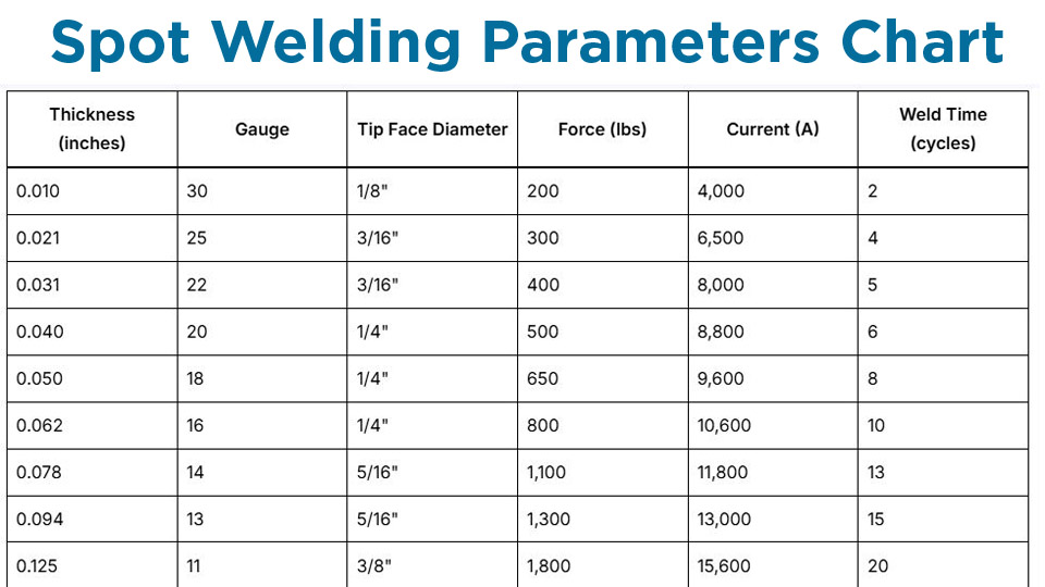
| Thickness (inches) | Gauge | Tip Face Diameter | Force (lbs) | Current (A) | Weld Time (cycles) |
|---|---|---|---|---|---|
| 0.010 | 30 | 1/8″ | 200 | 4,000 | 2 |
| 0.021 | 25 | 3/16″ | 300 | 6,500 | 4 |
| 0.031 | 22 | 3/16″ | 400 | 8,000 | 5 |
| 0.040 | 20 | 1/4″ | 500 | 8,800 | 6 |
| 0.050 | 18 | 1/4″ | 650 | 9,600 | 8 |
| 0.062 | 16 | 1/4″ | 800 | 10,600 | 10 |
| 0.078 | 14 | 5/16″ | 1,100 | 11,800 | 13 |
| 0.094 | 13 | 5/16″ | 1,300 | 13,000 | 15 |
| 0.125 | 11 | 3/8″ | 1,800 | 15,600 | 20 |
Metric equivalents for ~0.5–3 mm sheets typically use 2–6 kN force and 8,500–15,000 A. For coated mild steel, increase current 10–20%.
Stainless Steel
Stainless has higher electrical resistance but lower thermal conductivity, leading to quicker localized heating but greater distortion risk. Use higher force and often lower current than mild steel.
| Thickness (inches) | Gauge | Tip Face Diameter | Force (lbs) | Current (A) | Weld Time (cycles) |
|---|---|---|---|---|---|
| 0.010 | 32 | 1/8″ | 230 | 2,000 | 1 |
| 0.031 | 22 | 3/16″ | 650 | 4,800 | 3 |
| 0.050 | 18 | 1/4″ | 1,200 | 7,500 | 6 |
| 0.062 | 16 | 1/4″ | 1,500 | 9,000 | 7 |
| 0.125 | 11 | 3/8″ | 3,200 | 15,000 | 17 |
Increase force 20–30% over mild steel baselines. Shorter times minimize sensitization in austenitic grades. Class 2 or 3 electrodes are common; dress frequently.
Aluminum Alloys
Aluminum’s high conductivity demands high current, short time, and clean surfaces (oxide removal critical). MFDC machines perform better than AC.
| Thickness (inches) | Gauge | Tip Face Diameter | Force (lbs) | Current (A) | Weld Time (cycles) |
|---|---|---|---|---|---|
| 0.016 | 26 | 5/8″ | 200 | 14,000 | 1 |
| 0.032 | 20 | 5/8″ | 400 | 18,000 | 2–3 |
| 0.050 | 16 | 5/8″ | 500 | 22,000 | 4 |
| 0.063 | 14 | 5/8″ | 550 | 24,000 | 5 |
| 0.102 | 10 | 7/8″ | 800 | 32,000 | 8 |
Use larger electrode faces and consider forging pulses. Limits are typically lower than steel (reliable up to ~2–3 mm per sheet on capable machines).
Galvanized Steel
Zinc coating requires adjustments: higher current to penetrate the layer, increased force, and more frequent electrode dressing due to pickup.
Start with mild steel values but add 15–25% current and monitor for zinc vapor. Typical for 0.031″ (22 ga): ~450–800 lbs force, 9,500–14,000 A, 7–12 cycles.
Adjusting Parameters for Real-World Variables
Thickness and Stack-Up Effects
Weld time and current scale roughly with total stack thickness. For unequal thicknesses, base settings on the thinner sheet while ensuring penetration. Thicker combined stacks (>4–6 mm total) may need pulsation or three-phase equipment for heat control.
Electrode tip diameter follows ~5√t (mm) rule for the thinnest sheet. Maintain face diameter 1–2 mm larger than target nugget.
Machine Type and Power Considerations
Single-phase AC machines are common but limited for aluminum or thick stacks. MFDC or inverter machines offer better control, shorter times, and higher efficiency. Verify your machine’s duty cycle and secondary current capacity before pushing high settings.
Surface Condition and Coatings
Clean, oxide-free surfaces are essential—especially for aluminum. Coatings like zinc or galvannealed demand parameter shifts and more maintenance. Pre-cleaning or using specialized electrodes extends tip life.
Electrode Selection and Maintenance
Class 2 copper works for most steels; zirconium-dispersed or Class 1 for aluminum. Proper geometry (dome or flat) affects current density. Dress electrodes when faces mushroom or pick up material to restore consistent performance.
Testing and Quality Verification
Nugget Evaluation Methods
Perform peel tests or chisel tests on sample welds. Target nugget diameter: minimum 4√t, ideally 5√t or more. Measure button size after peeling; full button indicates good fusion. Cross-section macros provide deeper insight into penetration and defects.
Lobe Curves and Process Windows
Advanced users develop lobe curves plotting current vs. time for acceptable welds (no expulsion, adequate size). This defines the operating window and accounts for variations in production.
Common Weld Defects and Corrections
- Undersized/Cold Welds: Increase current or time incrementally (5–10%).
- Expulsion/Surface Burns: Increase force first, then reduce current or time.
- Sticking Electrodes: Higher force, shorter time, better cooling, or tip dressing.
- Cracking: Adequate hold time, lower heat input, or post-weld tempering pulses for sensitive materials.
Iterate with test welds on scrap matching your exact material and thickness.
Advanced Considerations for Production and Specialty Applications
Pulsation and Slope Control
Pulsation (multiple short current pulses) helps with thicker materials or coated sheets by managing heat buildup. Upslope/downslope softens the weld start/end, reducing expulsion and improving cosmetics.
Projection Welding Integration
For fasteners or embossed parts, parameters shift toward higher force and shorter times focused on projections. Consult specific charts for weld nuts/studs.
Material-Specific Challenges
High-strength steels (AHSS) narrow the window and may need specialized schedules to avoid martensite issues. Copper alloys require very high currents due to conductivity. Dissimilar metal combinations (e.g., steel-aluminum) often need intermediate layers or alternative processes.
Automation and Monitoring
Modern controls allow dynamic feedback on current, voltage, and resistance. Monitor dynamic resistance curves for process consistency in high-volume settings.
Decision-Making Summary for Optimal Spot Welds
Selecting the right spot welding parameters chart values is the foundation of reliable joints, but success comes from testing on your specific setup and materials.
Prioritize electrode force for contact, balance current and time for nugget size without defects, and maintain equipment religiously. For critical applications, validate with shear/tensile testing and metallographic examination.
The best welders treat parameters as dynamic—monitor secondary current and resistance in real time, adjusting for electrode wear and part fit-up variations. This separates consistent production quality from occasional success.
FAQ
What is the standard spot welding parameters chart for 1 mm mild steel?
For two 1 mm mild steel sheets, start with ~2.5 kN (550 lbs) force, 9,000–10,000 A, and 8–12 cycles (60 Hz). Adjust based on peel test results for a 5–6 mm nugget.
How do spot welding parameters differ for aluminum vs. steel?
Aluminum needs 2–3x higher current, much shorter weld times (often 1–5 cycles), larger electrode faces, and clean surfaces. Steel is more forgiving with lower currents and longer times.
Why does my spot weld have expulsion even with chart settings?
Common causes include insufficient electrode force, dirty surfaces, worn electrodes, or slightly high current. Increase force first, then fine-tune current downward.
Can one spot welding parameters chart work for all machines?
No—use charts as starting points. AC machines differ from MFDC in efficiency and control. Always verify against your equipment’s capabilities and perform test welds.