You pull the trigger on your MIG gun. The wire rolls out cleanly. Drive rolls turn. Gas flows if you are using shielding gas. Yet nothing happens at the joint—no spark, no arc, no weld pool.
This exact situation, where a MIG welder wire feeds but no arc appears, is one of the most common and frustrating failures in the shop.
It stops production, wastes wire, and leaves both hobbyists and professionals staring at a machine that seems half-alive. The feed system and the welding-power circuit are independent.
Wire can move while the electrical path that creates the arc is completely open. Understanding where that path breaks is the only reliable way to restore welding current without random part replacement.
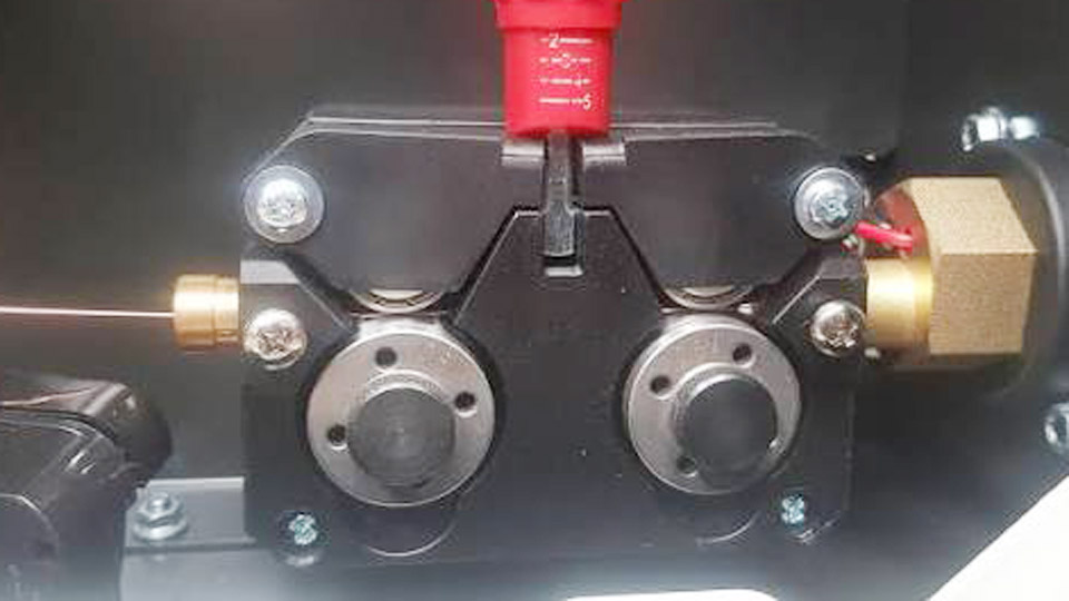
Image by mig-welding.co.uk
Why Wire Feed Continues When the Arc Fails
Separate Power Paths Inside the Machine
Most MIG machines route control voltage to the wire-feed motor through a trigger circuit that is independent of the main welding output. Closing the trigger switch energizes the feed motor and, on gas models, the solenoid.
The high-current welding circuit, however, travels from the power transformer or inverter through a contactor or solid-state switch, then out the gun cable to the contact tip.
If the contactor never closes, or if any connection between the tip and the workpiece is open, wire still feeds while open-circuit voltage never reaches the joint.
Measuring the Difference Between Open-Circuit and Welding Voltage
A healthy machine sitting idle shows open-circuit voltage (OCV) typically between 40 V and 70 V DC depending on the model and voltage setting. When the wire touches clean metal with a solid ground path, that voltage should collapse to the selected arc voltage (usually 16–28 V).
If a digital meter still reads full OCV while the wire is shorted to the workpiece, the high-current path is interrupted somewhere between the rectifier or inverter and the tip.
Ground Clamp and Work Connection Failures
Surface Contamination That Blocks Current
Paint, mill scale, rust, oil, and primer act as insulators. Even a clamp that feels tight on painted steel may pass only a few amperes—enough for the control circuit to sense contact in some machines, yet nowhere near the hundreds of amperes needed for an arc.
The clamp jaws must bite bright, bare metal. On structural steel this often means grinding a clean patch within a few inches of the weld start. On aluminum the oxide layer is even more stubborn; a stainless brush used only on aluminum is required.
Clamp Condition and Cable Continuity
Inspect the copper or brass jaws for deep pitting or melted spots. A clamp that has been used as a hammer or dropped repeatedly can lose spring tension and contact area. Measure resistance between the clamp jaws and the terminal that attaches to the machine.
Anything above 0.05 Ω under firm pressure indicates a problem in the cable strands or the terminal crimp. Many older ground cables develop broken strands near the clamp where the cable flexes constantly; the outer insulation still looks intact while the effective cross-section has been reduced by half.
Placement Relative to the Weld
Long ground paths through painted frames, bolted joints, or dirty tables introduce resistance that drops voltage before it reaches the arc. Clamp as close to the joint as practical and on the same piece of metal whenever possible. On multi-piece assemblies, avoid relying on temporary clamps or magnetic grounds that only contact through a thin film of scale.
Contact Tip and Gun Consumable Problems
How Current Transfers to the Wire
The contact tip is the final transfer point. Welding current jumps from the copper tip wall to the moving wire through a sliding electrical contact. Once the tip bore wears larger than the wire diameter by more than a few thousandths of an inch, the contact becomes intermittent. Spatter that bridges the tip to the nozzle can short the circuit to the gas diffuser and prevent current from reaching the wire at all.
Matching Tip Size to Wire Diameter
A 0.035-inch wire requires a tip marked 0.035 or 0.9 mm. Using a tip intended for 0.045-inch wire leaves too much clearance; the wire chatters inside the bore and the arc either fails to start or becomes unstable.
Conversely, forcing oversized wire through a small tip creates excessive drag, bird-nesting, and eventual tip burn-back. Replace tips as soon as the exit orifice shows an oval shape or visible scoring.
Diffuser, Nozzle, and Liner Contribution
A gas diffuser packed with spatter can reduce gas flow and also create an unintended ground path if metal bridges to the tip. The liner must be cut to the correct length for the gun; a liner that is too short allows the wire to buckle inside the cable and lose contact with the tip.
Excess liner length kinks and increases drag. Both conditions can prevent reliable electrical transfer even when the tip itself looks new.
Polarity and Process Selection Errors
Solid Wire Versus Flux-Cored Wire Requirements
Gas-shielded solid wire almost always runs electrode positive (DCEP). Self-shielded flux-cored wire usually runs electrode negative (DCEN). Reversing the leads on the machine output terminals changes polarity. When polarity is wrong, the arc may refuse to start or may establish only with extreme difficulty and excessive spatter.
Many machines have clearly marked terminals; others require the operator to move the gun lead and work lead to the correct posts. Confirm the wire manufacturer’s recommendation before assuming a hardware failure.
Machine Mode Switches and Synergic Settings
Inverter machines with process selector knobs can leave the output disabled if the dial is set to Stick or TIG while a MIG gun is connected. Synergic panels that ask for wire type and diameter will not deliver correct voltage if the wrong program is loaded. A quick check of the display or indicator lights against the selected process eliminates this simple error.
Cable, Connector, and Contactor Issues
DINSE and Twist-Lock Connections
Loose DINSE connectors at the machine panel or at the gun are frequent culprits. The connector can appear seated yet still have insufficient contact area if the locking collar is only partially engaged. Power the machine down, remove the connector, inspect the copper pins for arcing marks or oxidation, clean with fine abrasive if needed, and reseat firmly.
Internal Contactor or Relay Failure
On transformer machines the main contactor must close when the trigger is pulled. A burned contactor face or a failed coil leaves the secondary winding open. You will hear the feed motor run, but a meter across the output terminals will show no voltage change when the trigger is closed. Solid-state machines use SCR or IGBT modules that can fail open; diagnosis usually requires service-level testing.
Corroded Bus Bars and Terminals
Older machines sometimes develop corrosion on the heavy aluminum or copper bus bars that distribute welding current. Loose bolts or oxidized surfaces raise resistance enough to prevent usable current while still allowing control-circuit voltage to operate the feeder. Cleaning and retorquing these connections has restored many machines that appeared dead.
Voltage, Amperage, and Thermal Protection Effects
Settings Too Low to Establish an Arc
Extremely low voltage combined with high wire-feed speed can produce a cold short that never transitions into an arc. The wire simply stubs against the plate and piles up. Raise voltage in small increments while reducing wire speed until the arc ignites cleanly.
Charts supplied by the machine or wire manufacturer give starting points for a given thickness; treat them as starting points, not absolute values.
Thermal Overload Behavior
Many welders allow the wire feeder to continue running even after the thermal protector has opened the welding output. The machine may show a warning light or simply refuse to deliver current until it cools.
Undersized extension cords or low input voltage compound the problem by forcing the machine to draw higher current and heat faster.
Input Power and Breaker Considerations
A welder plugged into a circuit that cannot supply the required amperage may run the fan and feeder while the main transformer or inverter collapses under load. Measure input voltage at the receptacle under load; a drop of more than 5 % indicates an inadequate supply.
Systematic Diagnostic Sequence
External Checks Before Opening the Case
Begin at the work clamp, move to the contact tip, then the gun connector, polarity, and machine settings. These five points resolve the majority of “wire feeds but no arc” complaints. Only after these are verified should internal components be considered.
Using a Multimeter Effectively
Set the meter to DC voltage. Measure open-circuit voltage at the gun tip to work clamp with the trigger closed but the wire not touching metal. Then short the wire to the work and watch the voltage collapse.
No collapse means an open circuit somewhere in the high-current path. Continuity checks on the ground cable and gun lead (with power off) further isolate the break.
When to Stop and Call for Service
If external components are proven good, OCV is present, yet the voltage never collapses under short-circuit conditions, the fault is internal. Continued probing of live high-current circuits without proper training risks both personal injury and further machine damage. At that point the practical decision is professional diagnosis.
Preventing Recurrence Through Routine Inspection
Pre-Weld Visual and Mechanical Checks
Before striking an arc, glance at the contact tip for wear, confirm the ground clamp is on clean metal, and verify polarity matches the wire. These three actions take less than thirty seconds and eliminate most no-arc events.
Consumable Inventory and Replacement Intervals
Keep a small stock of the correct tip size, nozzles, and liners. Tips that have welded more than a few spools of wire are candidates for replacement even if they still look usable. Liners should be replaced when feeding becomes inconsistent or after several hundred pounds of wire, whichever comes first.
Cable Management and Storage
Avoid sharp bends in the gun cable and never use the ground clamp as a carrying handle. Store the machine with the gun cable loosely coiled so that internal conductors are not permanently deformed.
When the wire feeds but the arc refuses to appear, the decision tree is straightforward: verify the complete electrical circuit from tip to work clamp, confirm polarity and process settings, then examine connectors and contactor function. Most cases resolve with a clean ground, a fresh contact tip, or a properly seated cable.
Machines that still fail after these steps require internal service, but the time spent on external diagnosis prevents unnecessary board replacements and keeps the majority of welders productive.
Advanced operators also log the exact voltage and wire-speed combination that first re-establishes the arc; that data becomes a reliable baseline for future troubleshooting on the same machine and material combination.
FAQs
Why does my MIG welder feed wire but produce no spark?
A complete electrical circuit from the contact tip through the workpiece to the ground clamp is missing. The most frequent interruptions are a dirty or loose ground clamp, a worn contact tip, or incorrect polarity.
Can a bad contact tip stop the arc even if wire feeds normally?
Yes. Once the tip bore is oversized or clogged with spatter, current cannot transfer reliably to the wire. Replacing the tip with the correct size for the wire diameter restores the transfer path in most cases.
Does thermal overload allow the wire feeder to keep running?
Many machines keep the feed motor powered after the welding output has been disabled by the thermal protector. Allow the unit to cool fully and verify the warning indicator before assuming a deeper fault.
When should I suspect an internal contactor or board failure?
Only after the ground path, contact tip, gun connector, polarity, and machine settings have all been confirmed correct and open-circuit voltage is present but does not collapse when the wire shorts to the work.