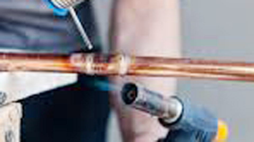
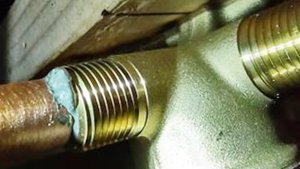
Solder refuses to wet stainless steel wire and simply balls up or rolls off the surface. That failure occurs because the chromium oxide layer on stainless blocks metallurgical bonding under ordinary flux and heat conditions.
Learning how to solder stainless steel wire correctly solves the problem by matching aggressive flux chemistry, silver-bearing alloys, and controlled heat input to the oxide barrier.
Without those three elements the joint remains mechanical at best and fails under vibration, thermal cycling, or corrosive service. Proper technique produces reliable capillary fill, color-matched beads, and corrosion resistance suitable for instrumentation, food-contact, or structural wire assemblies.
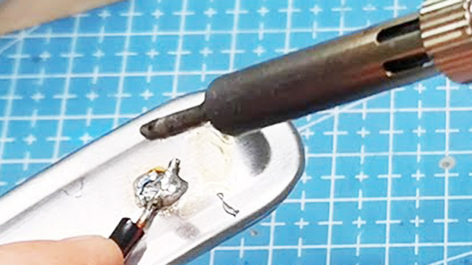
Image by @apourmaker6055
Why Standard Soldering Methods Fail on Stainless Wire
Ordinary electronics or plumbing practices collapse when applied to stainless because the surface chemistry differs fundamentally from copper or mild steel.
Chromium Oxide Barrier and Wetting Failure
Austenitic grades such as 304 and 316 form a continuous, self-healing chromium oxide film within seconds of exposure to air. This film is chemically stable and prevents molten tin-based solders from achieving atomic-level contact.
Standard rosin fluxes lack the acidity or halide activity needed to dissolve the oxide at soldering temperatures. The result is non-wetting: the solder remains spherical and the joint strength is limited to surface adhesion that peels under modest load.
When Regular Flux and Solder Produce Cold Joints
Plumbing fluxes formulated for copper and tin-lead solders without silver produce incomplete coverage and high residual stress at the interface.
On fine wire the problem intensifies because heat dissipates rapidly and the oxide reforms during the brief heating cycle. Joints that appear filled often contain voids or oxide inclusions that act as corrosion initiation sites once residual flux remains.
Selecting Flux and Solder Alloys for Stainless Steel Wire
Success depends on using materials specifically formulated to attack the oxide and provide adequate mechanical and corrosion performance.
Aggressive Flux Requirements and Chemistry
Phosphoric-acid-based fluxes or proprietary high-activity stainless fluxes (examples include Superior No. 71 or equivalent liquid/paste systems) supply the necessary oxide removal. These fluxes activate in the 100–370 °C range and remain effective long enough for the solder to wet.
Hydrochloric acid additions improve performance on molybdenum-bearing grades such as 316 but increase the risk of residual corrosion if cleaning is incomplete. Rosin or no-clean fluxes are ineffective on untreated stainless surfaces and should be reserved only for pre-tinned areas.
Silver-Bearing vs High-Tin Lead Solders
Tin-silver eutectic alloys such as Sn96/Ag4 (melting point approximately 221 °C) deliver superior wetting, higher strength, and better ductility than conventional tin-lead. The silver addition improves flow characteristics on stainless and reduces the tendency for galvanic attack in moist environments.
High-tin lead-bearing options (greater than 50 % tin, often with 1 % silver) remain usable where lead is permitted and cost is critical, but they offer lower corrosion resistance and darker color match. Lead-free tin-silver compositions are preferred for food-contact or potable-water service.
Matching Alloy to Service Conditions
Select Sn96/Ag4 or equivalent for general mechanical strength and color match. For elevated continuous service temperatures or higher joint strength requirements, evaluate higher-silver alloys or transition to brazing. Avoid pure tin or low-tin compositions; they produce brittle interfaces and poor long-term integrity on stainless.
Surface Preparation Decisions Before Heating
Surface condition determines whether the flux can reach the base metal before the oxide reforms.
Mechanical Abrasion vs Chemical Cleaning Sequence
Remove oils and greases with a solvent wipe, then abrade the joint area with stainless-steel wire brushes or fine abrasive cloth until a bright metallic surface appears. A controlled roughness improves mechanical keying without embedding foreign particles.
Perform soldering immediately after abrasion; delays allow oxide regeneration. Chemical cleaning with dilute acid solutions can supplement mechanical methods on heavily scaled wire, but residues must be neutralized and rinsed before flux application.
Pre-Tinning Options for Difficult Joints
When joint geometry restricts flux access or multiple wires must be joined, pre-tin each surface separately using the aggressive flux and silver-bearing solder.
Once the oxide is displaced and a thin solder coating is established, subsequent assembly can often proceed with milder flux because the tinned layer provides a wettable surface. Pre-tinning also protects cleaned surfaces during storage or complex fixturing.
Heat Source Selection and Temperature Control for Wire
Stainless steel’s relatively low thermal conductivity (especially austenitic grades) and high expansion coefficient demand uniform heating without localized overheating that anneals or melts fine wire.
Soldering Iron Limits on Fine Stainless Wire
High-wattage irons (80–150 W) or temperature-controlled stations set near 350–400 °C can succeed on small-diameter wire or single strands when thermal mass is low. The iron tip must transfer heat into the wire itself rather than simply melting the solder.
On multi-strand cables or thicker sections the iron frequently fails to bring the entire joint area above the flux activation temperature before the oxide reforms.
Torch Techniques Without Overheating Thin Sections
A small oxy-fuel, MAPP, or propane torch supplies the volume of heat needed for most stainless wire assemblies. Keep the flame reducing or neutral and move continuously to distribute heat. Aim for joint temperatures just high enough to activate the flux and melt the solder (typically 230–350 °C at the interface).
Excessive temperature causes grain growth, loss of mechanical properties in the wire, and excessive oxidation that the flux cannot overcome. Fixture the work to minimize distortion caused by the high coefficient of thermal expansion.
Joint Fit-Up and Capillary Action Execution
Clearance and heating sequence control whether solder is drawn into the joint or merely coats the exterior.
Maintain capillary gaps of 0.05–0.15 mm for optimal flow. Apply flux liberally to all faying surfaces. Heat the assembly until the flux becomes active (often indicated by boiling or clearing), then feed the solder to the joint entrance so capillary forces pull it through.
Avoid melting large amounts of solder on the torch or iron tip and transferring it; that practice produces cold joints and excess material. On multi-wire terminations or wrapped joints, ensure every strand reaches soldering temperature simultaneously to prevent unbonded interiors.
Post-Solder Cleaning and Corrosion Prevention
Aggressive fluxes leave hygroscopic and potentially corrosive residues. Immediate and thorough removal with hot water and mechanical agitation (non-metallic brush) is mandatory.
Detergent assists in emulsifying residues. Incomplete cleaning leads to delayed staining, pitting, or stress-corrosion cracking, particularly on 300-series alloys in chloride environments.
After cleaning, inspect the joint for continuous fillets without voids or oxide films. For critical service, verify electrical continuity or mechanical strength as appropriate to the application.
Wrapping Up
The decision between soft soldering and higher-temperature processes rests on required joint strength and service temperature. Soft-soldered stainless wire joints using Sn96/Ag4 and proper flux deliver adequate performance for instrumentation leads, mesh assemblies, and light structural ties when capillary fill is complete and residues are eliminated.
When tensile or shear loads exceed the capacity of soft solder or continuous temperatures approach 200 °C, shift to silver brazing alloys and appropriate high-temperature flux; the same surface-preparation principles apply but heat input and joint design change.
Pro-level consistency comes from treating the oxide barrier as the primary variable and measuring success by wetting angle and residue-free surfaces rather than by the amount of solder deposited.