
Undersized fillet welds fail under load because the throat—the shortest path from root to face—carries the stress, not the leg length shown on most drawings. Many fabricators specify a leg size, deposit the weld, then discover the actual throat falls short of design requirements.
Learning how to calculate throat thickness of fillet weld prevents that mismatch. The calculation converts the visible leg into the load-bearing dimension used in strength formulas, code acceptance, and inspection.
Getting it right avoids both under-strength joints and unnecessary over-welding that drives up heat input, distortion, and cost.
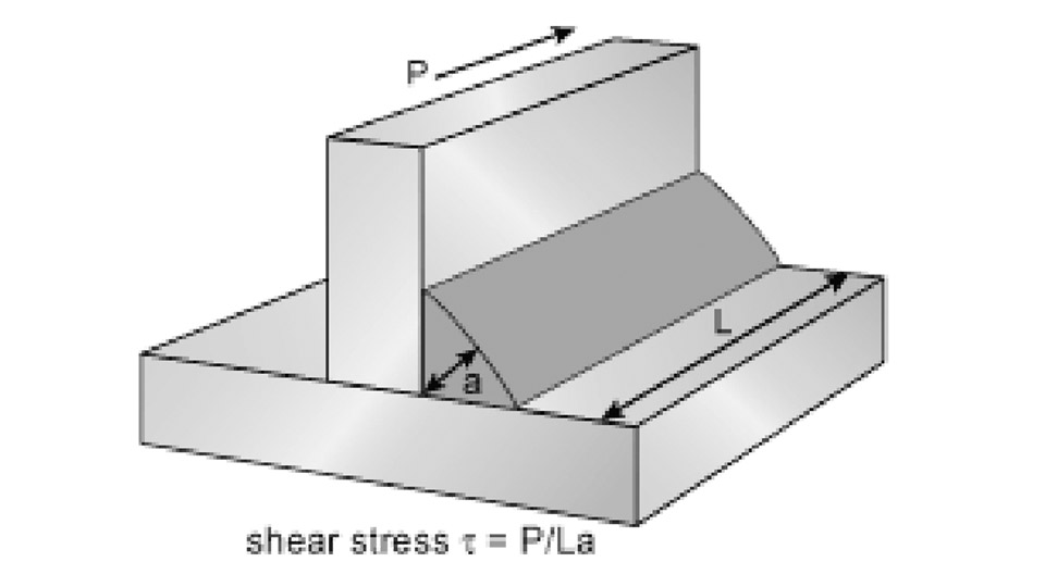
Image by twi-global
Core Formula for Equal-Leg Fillet Welds
For a standard equal-leg fillet in a 90° joint the theoretical throat thickness equals the leg size multiplied by 0.707.
Deriving the 0.707 Factor
The cross-section forms an isosceles right triangle. The throat is the altitude from the root (right-angle vertex) to the hypotenuse (weld face). Trigonometry gives:

where is throat thickness and is leg length. The same relation appears as . This value assumes fusion reaches the root but does not extend beyond it, and the face is flat.
Converting Between Leg Size and Throat
Reverse the equation when a design specifies throat rather than leg:

Example: a required throat of 6 mm demands a minimum equal leg of 8.48 mm; shops normally call out the next standard size (9 mm or ⅜ in). Conversely, a ¼ in (6.35 mm) leg produces a theoretical throat of 4.49 mm.
| Leg Size (mm) | Theoretical Throat (mm) | Leg Size (in) | Theoretical Throat (in) |
|---|---|---|---|
| 3 | 2.12 | 1/8 | 0.088 |
| 4 | 2.83 | 3/16 | 0.133 |
| 5 | 3.54 | 1/4 | 0.177 |
| 6 | 4.24 | 5/16 | 0.221 |
| 8 | 5.66 | 3/8 | 0.265 |
| 10 | 7.07 | 1/2 | 0.354 |
| 12 | 8.49 | 5/8 | 0.442 |
These values assume equal legs and a 45° face angle. Any deviation requires geometry adjustment.
Theoretical Throat vs Effective Throat vs Actual Throat
Codes and inspectors use three related but distinct terms.
When Codes Allow Penetration Credit
Theoretical throat is the pure geometric distance based on the inscribed triangle. Effective throat is the value used for strength calculations. In most AWS and AISC rules the two are identical for fillet welds made by SMAW, GMAW, or FCAW: effective throat = 0.707 × leg size. Submerged-arc welding (SAW) receives special treatment under AISC.
For SAW fillets ⅜ in and smaller the effective throat may equal the leg size; larger SAW fillets may add 0.11 in of penetration credit when procedure qualification demonstrates consistent deep fusion. Claiming that credit without documented penetration data is not permitted.
Impact of Convexity and Concavity
Actual throat is the measured distance from root to the real weld face. Convex reinforcement increases actual throat above theoretical; concave faces reduce it. Most codes base design on the theoretical (or effective) value and limit excess convexity to control stress concentration and inspection difficulty.
A concave profile that drops the actual throat below the required effective throat is rejectable. Measurement must therefore locate the true shortest path, not simply scale the face width.
Weld Throat Thickness Calculator
Calculating Throat for Unequal-Leg Fillets
Unequal legs appear when joint access, plate thickness, or load direction favors one side. The simple 0.707 factor no longer applies.
Geometric Method for Minimum Distance
The theoretical throat remains the shortest distance from the root to the weld face. Construct the largest right triangle that fits inside the weld cross-section using the two unequal legs as the sides. The altitude to the hypotenuse is the throat. For legs and the throat is:
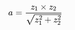
Example: legs 6 mm and 10 mm yield mm. The smaller leg still governs size designation under AWS (the size is the shorter leg), yet strength calculations use the calculated throat. When the dihedral angle differs from 90°, the angle itself enters the trigonometry and further reduces or increases the throat for the same leg lengths.
Code Differences That Change the Numbers
Drawing call-outs and acceptance criteria diverge by standard.
AWS / AISC Approach (Leg Size Focus)
AWS D1.1 and AISC specify fillet welds by leg size. Minimum leg sizes are tabulated against the thicker part joined. Strength is still computed on the effective throat (0.707 × size for non-SAW).
Inspectors verify both legs with fillet gauges; undersize on either leg is nonconforming even if the measured throat meets the design value. Maximum size is often limited to the thickness of the thinner part to avoid over-welding.
ISO / EN Approach (Throat Designation)
ISO 2553 and EN standards commonly designate the throat thickness ( a ) directly on the drawing. Fabricators must then deposit enough metal to achieve that throat, which normally requires a leg of approximately 1.414 × .
European design rules also use the throat area for stress checks, so the conversion is built into the design process rather than added later. When working to mixed codes, convert every call-out to a consistent basis before welding begins.
Using Throat Thickness in Strength Calculations
Once throat is known, weld capacity follows directly.
Shear Stress on Throat Area
Design stress is load divided by the effective area:
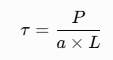
where is the applied force, is effective throat, and is effective weld length. Allowable or design shear stress depends on electrode strength and code (commonly 0.3 × electrode tensile strength under older ASD rules, or factored values under LRFD/Eurocode).
Parallel and transverse loading produce different stress states; transverse fillets develop higher resultant stress and often receive higher allowable values in some codes. Always confirm the governing load direction before sizing.
Measuring Throat Thickness on the Shop Floor
Calculation is useless without verification.
Fillet gauges measure leg size directly. Throat gauges or a combination square and scale measure the actual distance from root to face when access allows. For critical joints, sectioning a run-off tab or using ultrasonic methods confirms internal fusion to the root.
When convexity is present, the gauge must contact the true face, not ride on the reinforcement. Record both calculated theoretical throat and measured actual throat; the smaller value governs acceptance against the design requirement.
Selecting the correct throat thickness starts with the governing code’s definition of effective throat, converts any leg-size call-out through the appropriate geometric factor, and verifies the deposited weld against that number.
Advanced fabricators further optimize by qualifying deep-penetration procedures that legitimately increase effective throat, reducing deposited volume while preserving design capacity on high-volume fillet work.


