Incorrect settings for TIG welding mild steel produce immediate, visible failures: thin sheet melts through in seconds, thicker plate shows incomplete fusion at the root, or the tungsten ball melts and contaminates the puddle.
These problems stem from mismatched amperage, wrong polarity, insufficient gas coverage, or improper tungsten preparation. Correct parameters deliver controlled heat input, clean arc starts, and consistent penetration without excess reinforcement or undercut.
Because mild steel conducts heat rapidly and tolerates a relatively wide process window, precise starting values based on thickness, joint type, and position allow rapid fine-tuning with the foot pedal.
Getting the baseline right first eliminates most porosity, tungsten inclusions, and distortion before the first production bead is laid.
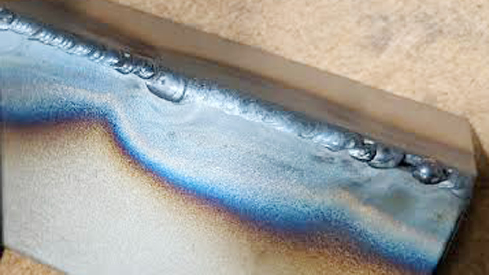
Image by r/Welding
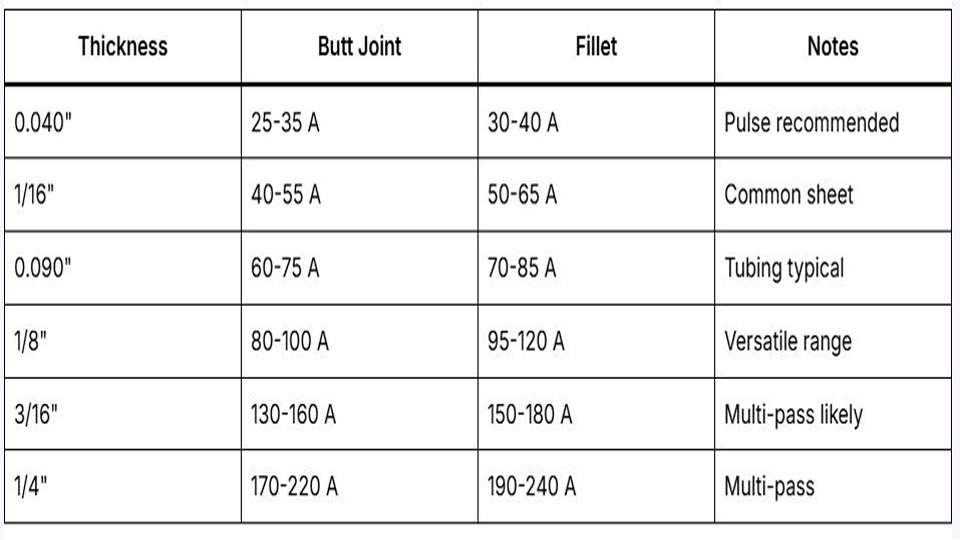
Core Amperage Ranges by Mild Steel Thickness
Amperage is the primary heat-control variable. The industry baseline of roughly 1 amp per 0.001 inch of thickness provides a reliable starting point on DCEN, then adjusted for joint geometry and travel speed.
Thin Gauge Sheet (0.035–0.090 inch)
Start between 30–90 A. On 16–18 gauge, 40–70 A with a 1/16-inch tungsten keeps the puddle fluid without burn-through. Travel speeds of 8–12 ipm and short arc length (electrode diameter or less) prevent excessive heat buildup. Fillet joints on this thickness often need 5–10 A more than butt joints because heat sinks into two planes.
Medium Thickness Plate (1/8–3/16 inch)
The working window sits at 80–180 A. A 1/8-inch closed butt joint typically starts at 100–130 A with 3/32-inch tungsten and 3/32-inch ER70S-2 filler. Fillet joints move toward the upper end (120–160 A) to ensure fusion at both toes. Open-root butts drop 10–15 A to avoid excessive root reinforcement.
Heavier Sections (1/4 inch and Above)
Expect 150–280 A. Single-pass 1/4-inch plate runs cleanly at 150–200 A with 1/8-inch tungsten. Multi-pass work on 3/8-inch material often begins the root at 180–220 A, then raises slightly for fill passes once the joint is preheated by previous beads. Beyond 3/8 inch, many shops limit TIG to the root pass and switch processes for fill to maintain productivity.
| Thickness | Typical Amps (Butt) | Typical Amps (Fillet) | Tungsten | Filler | Cup | Argon Flow |
|---|---|---|---|---|---|---|
| 0.035–0.060″ | 30–60 | 40–70 | 1/16″ | 0.040–1/16″ | #4–#6 | 10–15 CFH |
| 1/16–3/32″ | 60–100 | 70–110 | 1/16–3/32″ | 1/16–3/32″ | #5–#7 | 15–20 CFH |
| 1/8″ | 90–130 | 110–150 | 3/32″ | 3/32″ | #6–#8 | 15–20 CFH |
| 3/16″ | 120–170 | 140–190 | 1/8″ | 1/8″ | #7–#8 | 20–25 CFH |
| 1/4″ | 150–200 | 170–230 | 1/8″ | 1/8″ | #8–#10 | 20–25 CFH |
| 3/8″ | 200–260 | 220–280 | 5/32″ | 3/16″ | #8–#10 | 20–30 CFH |
Polarity and Power Source Decisions for Mild Steel
Mild steel requires DC electrode negative (DCEN / DC–). This polarity places approximately 70 % of the heat in the workpiece and only 30 % at the tungsten, producing a narrow, deep-penetrating arc with minimal electrode wear.
Why AC Is Incorrect for Steel
AC balances heat between electrode and work and provides oxide-cleaning action needed for aluminum. On mild steel it produces a wider, shallower puddle, faster tungsten degradation, and higher risk of undercut at equivalent amperage. Machines must be locked in DC TIG mode before striking an arc.
Foot Pedal Versus Panel Control
Most operators set the machine maximum 10–20 % above the target amperage and modulate with the foot pedal. This allows low-amp starts to establish the puddle, full current during travel, and a controlled downslope to fill the crater. Panel-only machines require precise preset values and careful slope-up/slope-down programming if available.
Tungsten Selection, Preparation, and Stick-Out
Electrode choice and grind geometry directly affect arc stability and contamination risk.
Preferred Electrode Types and Diameters
2 % lanthanated (gold or blue band) is the current preferred electrode for DC mild-steel work: excellent low-amp starts, low erosion, and stable arc across the full current range. 2 % thoriated remains effective but carries handling restrictions in some regions. Match diameter to current:
- 1/16 inch: up to approximately 120–150 A
- 3/32 inch: 80–200 A
- 1/8 inch: 150–300 A+
Grind Geometry and Stick-Out Length
Grind longitudinally to a 20–30° included angle with a slight truncated tip for currents above 100 A. A long taper concentrates the arc; a blunt tip spreads it. Stick-out beyond the cup should equal electrode diameter or slightly less with a standard collet body.
Gas-lens collet bodies allow stick-outs up to ½ inch while maintaining laminar flow, reducing the chance of tungsten contamination on out-of-position joints.
Shielding Gas Flow, Cup Size, and Coverage
100 % argon is the standard shielding gas. Flow rate and cup geometry determine whether the puddle remains protected.
Matching Cup Size to Flow Rate
A practical rule is roughly twice the cup number in CFH as a minimum (e.g., #7 cup ≈ 14 CFH). Common shop ranges:
- Thin material / small cups (#4–#6): 10–18 CFH
- Medium work (#7–#8): 15–22 CFH
- Heavy plate or drafty conditions (#8–#10): 20–30 CFH
Excessive flow creates turbulence that aspirates air into the shield and produces porosity. Gas lenses straighten the flow column, often allowing a 20–40 % reduction in CFH while improving coverage.
Pre-Flow and Post-Flow Timing
Pre-flow of 0.5–1.0 second purges the cup before the arc starts. Post-flow of 5–12 seconds (longer at higher amperage) protects the solidifying weld and the hot tungsten tip from oxidation. Insufficient post-flow leaves a blackened tungsten that must be re-ground.
Filler Metal Choices and Feed Technique
ER70S-2 and ER70S-6 are the two primary AWS A5.18 classifications used for mild steel.
When to Select ER70S-2 Versus ER70S-6
ER70S-2 contains additional deoxidizers and tolerates light mill scale or residual oxide better, making it preferred for root passes and less-than-perfectly-cleaned joints.
ER70S-6 offers higher silicon and manganese for improved wetting and fluidity on clean, multi-pass work. Both produce 70 ksi tensile strength deposits matching typical mild-steel base metals.
Diameter Matching and Dip Technique
Filler diameter is usually equal to or one size smaller than base-metal thickness up to 1/8 inch; above that, step up one size to maintain deposition without overheating the rod. Keep the filler tip inside the gas envelope at all times.
Dip the rod into the leading edge of the puddle rather than melting it with the arc itself; this minimizes oxidation of the filler and produces a cleaner bead profile.
Adjustments for Joint Type and Welding Position
Baseline amperage assumes flat-position closed butt joints on clean plate. Real joints require systematic offsets.
Fillet Versus Groove Joints
Fillets demand 10–20 A more than equivalent-thickness butts because heat dissipates into both members. Outside corners often run cooler than inside corners. Open-root grooves need reduced current and tighter arc length to control the root bead without excessive melt-through.
Vertical and Overhead Reductions
Vertical-up and overhead positions typically require a 10–15 % amperage reduction relative to flat. Shorter arc length and slightly faster travel help support the puddle against gravity. Vertical-down is rarely used for mild-steel TIG because of incomplete fusion risk at the root.
Machine Features That Improve Consistency
Modern inverter machines offer pulse, slope, and start-current controls that expand the usable process window.
Pulse Settings for Thin Material
Low-frequency pulse (0.5–2 Hz) or higher-frequency pulse (20–100 Hz) reduces average heat input while maintaining peak current for fusion. Background current is commonly set at 20–40 % of peak. This combination limits distortion on sheet-metal assemblies and improves control on open-root pipe.
Start Current and Slope Programming
A low start current (15–30 A) followed by a short upslope lets the operator position the torch and establish the puddle before full amperage arrives. Downslope of 1–3 seconds fills the crater and reduces the chance of crater cracking on higher-carbon or restrained joints.
Wrapping Up
Correct settings for TIG welding mild steel begin with DCEN polarity, thickness-based amperage near 1 A per 0.001 inch, matching tungsten and filler diameters, and argon flow matched to cup size. Once those baselines are locked, joint geometry and position dictate the final offsets of 5–20 A.
The resulting arc produces a quiet, focused column, a fluid but controllable puddle, and a bead that requires minimal post-weld cleanup.
Advanced operators further refine heat input by combining short-arc technique with deliberate pulse frequency and crater-fill programming, allowing single-pass quality on thicknesses that previously required multi-pass sequences.
FAQs
What amperage for TIG welding 1/8 inch mild steel?
Start at 90–130 A DCEN for a closed butt joint with 3/32-inch tungsten and 3/32-inch ER70S-2 filler. Raise 10–20 A for fillets; lower 10–15 A for open-root work.
What gas flow rate for TIG on mild steel?
15–20 CFH argon covers most #6–#8 cups on 1/16–1/4 inch material. Increase to 20–25 CFH for larger cups or drafty conditions; reduce with a gas lens.
DCEN or DCEP for TIG welding mild steel?
Always DCEN (electrode negative). DCEP overheats the tungsten rapidly and produces a wide, shallow arc unsuitable for steel.
What tungsten size for TIG welding 1/4 inch mild steel?
1/8-inch 2 % lanthanated tungsten handles the typical 150–200 A range. Sharpen to a 20–30° taper and maintain stick-out equal to electrode diameter or less.