A heavy transformer stick welder that demands a dedicated 50-amp circuit and a cart just to move across the shop creates the same problem every time a job moves outdoors or onto thin material: limited control and excess heat input.
What is an inverter welder answers that limitation by replacing the large iron-core transformer with high-frequency solid-state electronics.
The result is a machine that weighs a fraction of its predecessor, draws less line current for the same output amperage, and delivers faster arc response.
For DIY welders, hobbyists, students, and professionals, understanding the conversion process, real efficiency numbers, duty-cycle behavior, and environmental limits determines whether the technology solves the job or introduces new constraints around power quality and component durability.
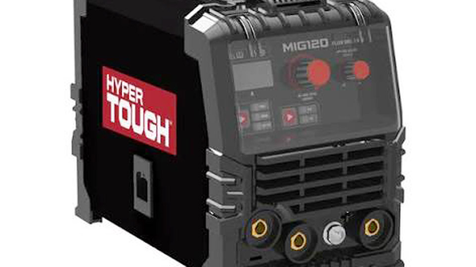
Image by builders
How High-Frequency Switching Changes Welding Power Delivery
Traditional machines step down 50/60 Hz line power through a massive transformer. An inverter first rectifies incoming AC to DC, then uses IGBT or MOSFET transistors to chop that DC into high-frequency AC (typically 20–100 kHz) before it reaches a much smaller transformer.
Rectification and High-Frequency Inversion Stages
Incoming 120 V or 240 V AC passes through a full-wave rectifier and filter capacitors, producing a stable high-voltage DC bus. IGBT modules then switch this DC on and off tens of thousands of times per second, creating a high-frequency square-wave or modified waveform.
Because transformer size scales inversely with frequency, the magnetic core can shrink dramatically while still transferring the required power.
The high-frequency AC is stepped down and rectified again to produce smooth DC welding current (or controlled AC for aluminum TIG).
Why Switching Frequency Controls Size and Response
At 60 Hz a transformer core must be large enough to handle the magnetic flux without saturation. Raising the frequency to 20–50 kHz reduces the required core area and number of turns by roughly the same factor.
The smaller magnetics lose less energy as heat and allow the control electronics to sample and correct the arc hundreds of times faster than a conventional machine.
This rapid feedback enables features such as adjustable hot start, arc-force, and pulse waveforms that were impractical on pure transformer designs.
Weight, Efficiency, and Duty-Cycle Numbers That Affect Real Jobs
The physical and electrical differences translate directly into usable performance metrics.
Portability and Input Current Draw
A 200 A class inverter commonly weighs 9–20 kg (20–45 lb). Equivalent transformer machines often exceed 40–90 kg. Because conversion efficiency reaches 85–95 % versus 55–70 % for many transformer units, the same 200 A output draws roughly 25–35 A on a 240 V circuit instead of 45–60 A.
Many dual-voltage inverters therefore operate useful stick or TIG currents from a standard 20 A 120 V outlet, something rarely practical with older designs.
Duty-Cycle Behavior Under Continuous Load
Inverter ratings of 60 % at full output are common; some industrial models reach 100 % at reduced amperage. A 60 % duty cycle at 200 A means six minutes of welding followed by four minutes of cooling within a ten-minute period.
The compact heat sinks and forced-air cooling dissipate losses quickly because the thermal mass is low. Transformer machines of similar output often sit at 20–40 % duty cycle because the large core retains heat longer.
On intermittent shop work the difference is minor; on long structural seams or production runs the higher rating reduces forced pauses.
Arc Characteristics and Multi-Process Capability
The fast control loop changes how the arc behaves across processes.
Stick (SMAW) Response and Electrode Compatibility
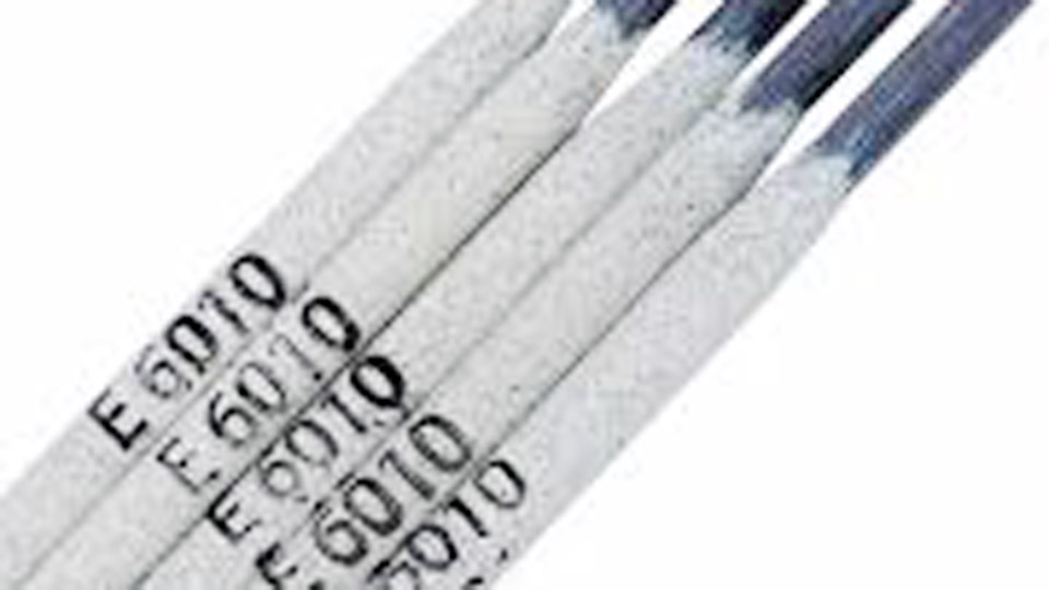
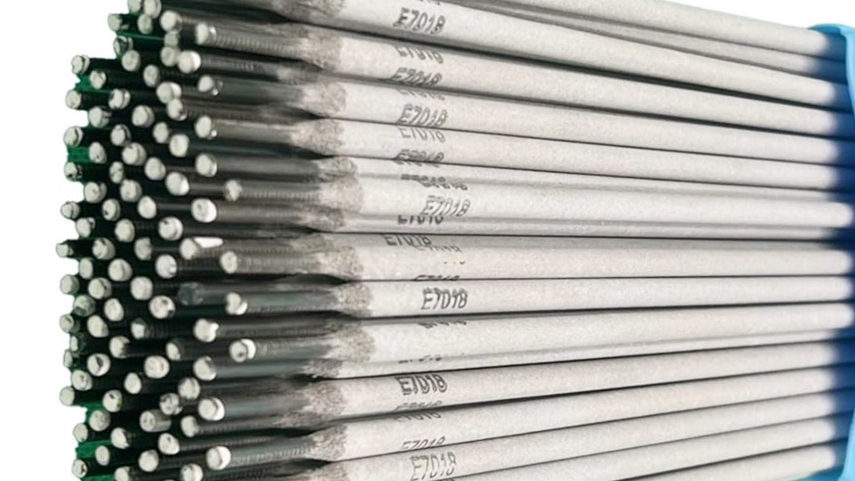
Most inverter stick machines output DC, giving a quieter, more directional arc than pure AC transformer units. Adjustable arc-force increases current when the voltage drops (short arc or electrode dig), reducing sticking with 7018 or 6010 rods. Hot-start briefly raises current at ignition for reliable starts on cold or dirty metal.
Open-circuit voltage is typically high enough for low-hydrogen electrodes while still incorporating voltage-reduction devices on many professional models.
TIG and MIG Performance Gains
On TIG, high-frequency start or lift-arc is standard, and AC balance and frequency controls become practical. Raising AC frequency from 60 Hz to 100–200 Hz narrows the arc cone for better control on thin aluminum.
Pulse functions reduce average heat input 20–30 % while maintaining penetration, useful on sheet metal or out-of-position stainless. MIG inverters often include inductance or waveform control that softens the arc transfer, lowering spatter on short-circuit transfer.
Multi-process machines combine stick, TIG, and MIG in one chassis because the same power stage can be reconfigured by software and output circuitry.
Limitations When Power Quality or Environment Changes
Inverter advantages reverse under certain field conditions.
Generator Compatibility and Harmonic Distortion
Inverters rely on clean DC bus voltage. Generators with high total harmonic distortion (THD above 5–6 %) or large voltage spikes can damage capacitors and IGBT modules. Many manufacturers specify “clean power” or inverter-rated generators.
Units with power-factor correction (PFC) tolerate wider input voltage swings and present a more resistive load to the generator, improving compatibility. Without PFC or voltage sensing protection, a long cable run or overloaded generator can trigger thermal shutdown or permanent failure.
Dust, Moisture, and Repair Considerations
Open-frame or poorly sealed inverters accumulate conductive dust on circuit boards. Moisture on high-voltage sections causes tracking.
Industrial models with better IP ratings and conformal coatings survive shop environments longer, yet component-level repairs remain more specialized and costly than replacing a transformer winding.
Expected service life under daily professional use is often cited in the 8–12 year range versus 15–25+ years for robust transformer machines, though actual results depend on cooling maintenance and duty.
Selecting Output Rating and Features for Specific Work
Matching the machine to the dominant process and environment avoids both under- and over-specification.
Amperage and Process Priorities
For light fabrication and repair on material up to ¼ in, a 140–180 A dual-voltage inverter covers most stick and TIG needs. Structural or heavy plate work pushes toward 200–250 A machines with higher duty-cycle ratings.
If aluminum TIG is required, confirm AC output and adjustable balance/frequency. Pure stick users can accept simpler DC-only units; multi-process flexibility adds cost but consolidates equipment.
Input Power and Job-Site Constraints
Confirm available circuit capacity before purchase. A 200 A inverter on 240 V typically needs a 30–40 A breaker; higher-output models may require 50 A. For remote sites, verify generator THD limits and whether the welder includes PFC or wide-input-voltage tolerance.
Cable length and ground integrity still matter—voltage drop on the primary side reduces available output the same way it does on any machine.
Wrapping Up
Choosing an inverter welder centers on whether the reduction in weight, increase in efficiency, and improvement in arc control outweigh greater sensitivity to power quality and environmental contamination.
When the majority of work stays on stable shop power and involves position changes or thinner sections, the technology delivers measurable gains in productivity and weld quality.
On remote structural sites with marginal generators and heavy continuous stick welding, a well-built transformer machine can still prove more durable.
Advanced operators further exploit inverter capability by combining short-arc technique with programmed pulse parameters to control heat input on high-restraint joints without changing electrode size or travel speed.