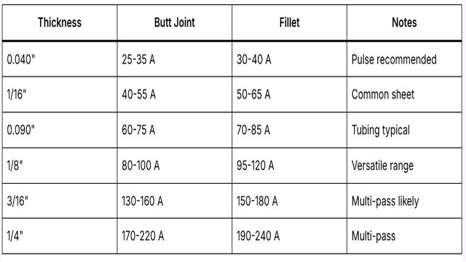
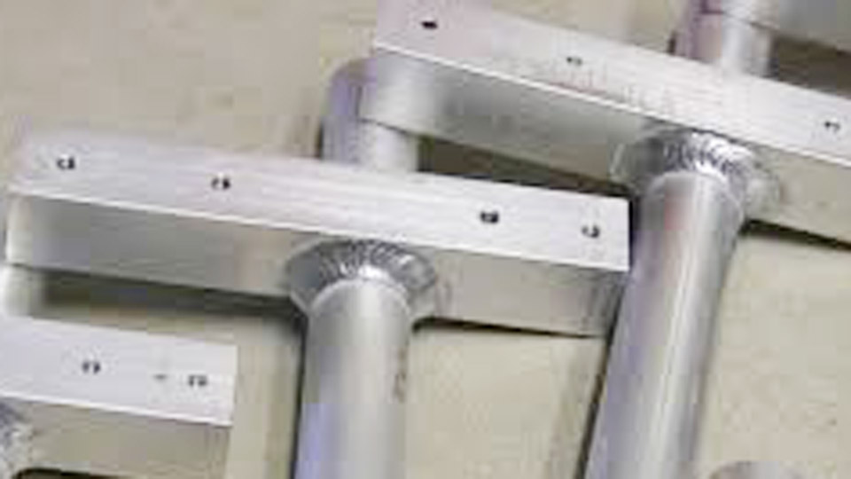
Burn-through on 16-gauge stainless or sudden warping on thin aluminum tubing often appears midway through a continuous-current TIG pass when the puddle suddenly expands beyond control.
A pulse TIG welder solves this by rapidly alternating the welding current between a high peak value and a lower background value, delivering penetration only in short bursts while the background phase lets the metal cool.
This cyclic heat input shrinks the heat-affected zone, stabilizes the puddle in out-of-position work, and produces consistent bead profiles that continuous TIG cannot match on heat-sensitive or thin-gauge material.
Understanding the process matters because the difference between a usable joint and scrap frequently comes down to whether the machine can modulate current this way and whether the operator sets the four primary parameters correctly.
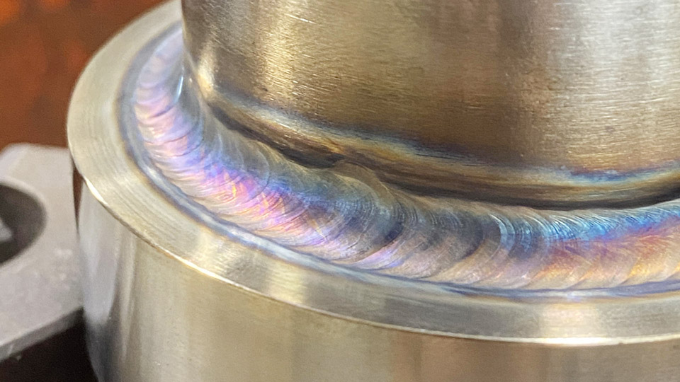
Image by r/Welding
How Pulse TIG Differs from Continuous Current Output
Continuous TIG holds a steady amperage once the foot pedal or torch control reaches the set point. The puddle grows at a constant rate, and heat continues to conduct into the base metal for the entire travel time.
Pulse TIG replaces that steady output with a square or near-square waveform that switches between two discrete current levels many times each second.
Peak Current Versus Background Current Roles
Peak current supplies the energy needed for fusion and penetration. Background current keeps the arc lit at a fraction of peak—typically 20–50 %—so the puddle can partially solidify between peaks.
Average heat input therefore drops even when peak amperage is set higher than a continuous-current equivalent. On thin stainless the background phase prevents the metal from reaching the temperature where carbide precipitation or excessive grain growth occurs.
Arc Constriction at Higher Frequencies
As pulse frequency rises, electromagnetic forces inside the arc column intensify. The arc becomes narrower and more directional, which concentrates energy into a smaller spot.
This constriction is the reason high-frequency pulse can achieve deeper penetration on a given average current than continuous TIG while still limiting overall heat input.
Core Pulse Parameters That Determine Heat Input and Bead Shape
Four adjustable values define every pulsed waveform. Changing any one alters both thermal behavior and visual appearance.
Pulse Frequency (Pulses Per Second)
Frequency sets how many complete peak-to-background cycles occur each second. Low rates (0.5–5 PPS) produce distinct, visible ripples and give the operator a clear rhythm for filler addition. Mid-range values (10–50 PPS) smooth the bead while still reducing heat.
High rates (100–500 PPS or higher on advanced inverters) stiffen the arc, narrow the bead, and allow faster travel with minimal visible pulsing. Frequencies between roughly 10 and 30 PPS can create a distracting strobe effect for some operators and are often avoided.
Peak Time or Pulse Width Percentage
This value controls the fraction of each cycle spent at peak current. A 40 % peak time delivers less total energy than a 60 % setting at the same frequency and amperages. Wider peak times increase penetration and bead width; narrower times maximize cooling. Most starting points fall between 40 % and 60 %.
Background Current Percentage
Background is almost always expressed as a percentage of the peak amperage setting. Values of 25–40 % give the strongest heat reduction. Raising background toward 50 % keeps the puddle more fluid and supports higher travel speeds, while dropping it toward 15–20 % maximizes cooling for the thinnest gauges or gap-bridging situations.
Interaction with Foot-Pedal or Torch Control
On most machines the peak amperage is still modulated by the foot pedal or fingertip control. The pulse parameters ride on top of that operator-controlled peak.
This arrangement lets the welder reduce overall heat mid-weld simply by easing off the pedal while the pulse waveform continues to operate at the reduced peak level.
When Pulse TIG Delivers Measurable Advantages Over Standard TIG
Pulse is not required for every joint, but specific conditions make the difference quantifiable.
Thin-Gauge and Heat-Sensitive Alloys
On material thinner than about 1/8 in (3.2 mm), especially stainless, titanium, or nickel alloys, continuous current quickly builds heat that continuous conduction cannot remove. Pulse reduces average heat input enough to keep distortion and discoloration within acceptable limits while still achieving full fusion.
High-frequency pulse further shrinks the heat-affected zone, which helps preserve corrosion resistance in stainless by limiting time spent in the sensitization temperature range.
Out-of-Position and Overhead Work
Gravity pulls a large fluid puddle downward. The background phase lets the weld metal freeze enough to resist sagging between peaks. Operators can therefore maintain a more consistent bead profile on vertical-up and overhead joints without constant pedal dancing.
Cosmetic and Precision Bead Requirements
Low-frequency pulse synchronized with filler dips produces the classic stacked-dime appearance. High-frequency pulse yields a smoother, narrower bead with less post-weld finishing. Both outcomes reduce grinding and polishing time on architectural or sanitary stainless work.
Practical Parameter Ranges for Common Materials and Thicknesses
Settings are always refined on scrap of identical thickness and joint geometry, yet reliable starting windows exist.
Stainless Steel Thin Sheet and Tubing
For 0.040–0.062 in (1–1.6 mm) 304 or 316, a common starting combination is peak current 80–110 A, background 25–35 %, peak time 40–50 %, and frequency 1–3 PPS for visible rhythm or 50–150 PPS for tighter heat control.
Back-purging remains essential for full-penetration pipe or tube. Higher frequency reduces heat tint and the need for aggressive post-weld cleaning.
Aluminum Sheet and Light Plate
Aluminum’s high thermal conductivity requires higher peak currents than stainless of the same thickness. On 1/16–1/8 in material in AC mode, peak values of 100–150 A, background 30–50 %, peak time 40–60 %, and frequencies from 1–2 PPS (manual timing) up to 50–100 PPS are typical.
AC balance still governs cleaning action; pulse is applied on top of the AC waveform. Excessive background reduction can leave lack of fusion because aluminum needs continuous heat to overcome the oxide and rapid heat sink.
Carbon Steel and Mild Steel Thin Sections
Mild steel tolerates more heat, so pulse is used mainly for distortion control or to establish a consistent filler cadence. Peak currents follow normal continuous-current recommendations for thickness, background 25–40 %, and frequencies in the 1–10 PPS range for training or aesthetic control.
Machine Features Required for Effective Pulsed Operation
Not every TIG power source offers usable pulse. Entry-level machines may provide only a fixed or limited-range pulser. Full control requires independent adjustment of frequency, peak time, and background percentage, plus sufficient pulse frequency range (ideally to at least 100–200 PPS).
Inverter technology enables the rapid current switching that older transformer machines cannot achieve cleanly. Some advanced units add dual-pulse or pulse-on-pulse waveforms that further refine bead appearance, but these remain secondary to correct basic parameter selection.
Limitations and Situations Where Continuous TIG Remains Preferable
On thick plate where maximum deposition rate is the goal, the intermittent cooling of pulse reduces average heat input and can slow travel speed. Parameter complexity also increases setup time; an experienced operator can often match heat control on moderate thicknesses simply by modulating the foot pedal.
Pulse does not compensate for poor fit-up, contaminated material, or incorrect tungsten preparation. In high-production environments that already use automation or specialized continuous-current techniques, adding pulse may introduce more variables than benefits.
Wrapping Up
Selecting a pulse-capable TIG welder is justified when the work regularly involves thin gauge, stainless, aluminum, or out-of-position joints where heat control directly affects reject rates and finishing time.
The decisive technical choice is matching frequency and background percentage to the thermal conductivity and thickness of the specific alloy rather than treating pulse as a universal improvement.
Once those parameters are locked, the arc itself becomes a more predictable tool, allowing higher travel speeds and tighter heat-affected zones than continuous current can deliver on the same material.
FAQs
What does pulse frequency do on a TIG welder?
Pulse frequency sets how many times per second the current switches between peak and background. Low frequencies (1–5 PPS) create visible ripples and a timing rhythm for filler; high frequencies (100+ PPS) constrict the arc, narrow the bead, and reduce heat input.
Can I use pulse TIG on aluminum?
Yes. Pulse is applied on top of the AC waveform. It helps control heat on thin aluminum, but peak current must still be high enough to overcome the oxide and rapid heat sink; excessive background reduction can cause lack of fusion.
Does every TIG welder have pulse capability?
No. Basic machines often lack adjustable pulse or offer only limited frequency ranges. Full control of frequency, peak time, and background percentage requires an inverter with dedicated pulse circuitry.
Is pulse TIG better for beginners?
Low-frequency pulse can help a new welder develop a consistent rhythm for adding filler, but the extra parameters also increase complexity. Many instructors recommend mastering continuous-current puddle control first.