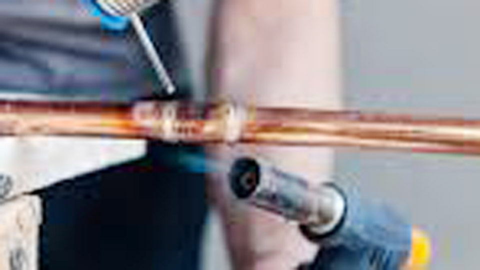
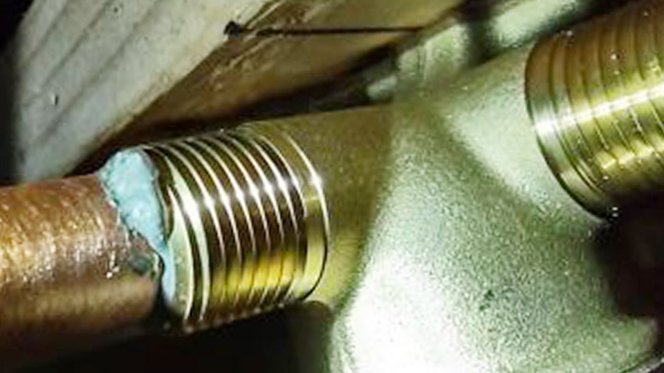
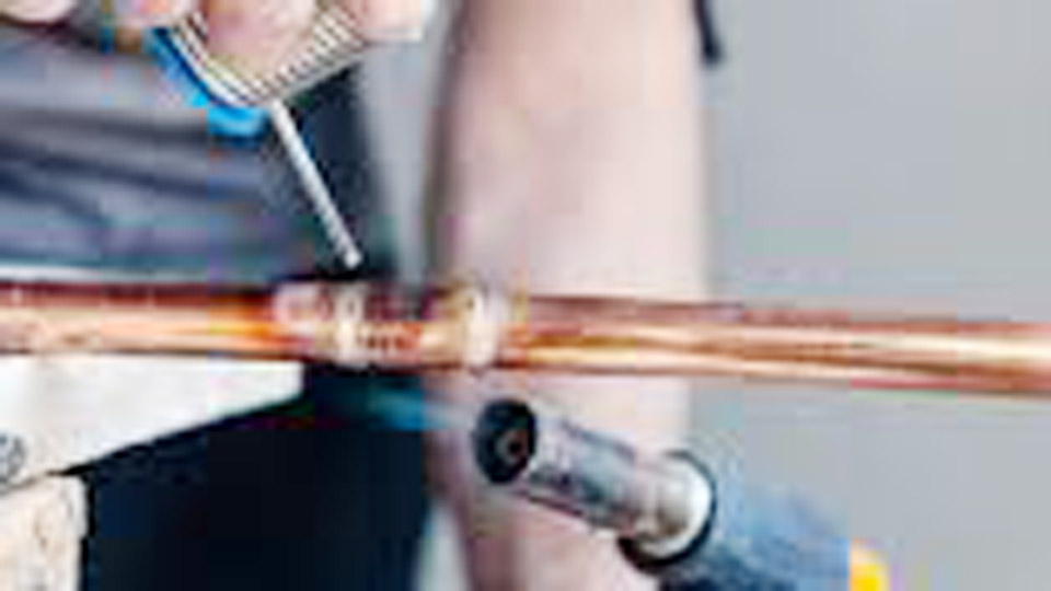
Leaking copper joints after the first pressure test almost always trace back to incomplete cleaning, uneven heat, or residual moisture that stops solder from flowing by capillary action.
Learning how to solder copper pipe for beginners starts with controlling those three variables rather than chasing higher flame temperatures or more solder.
A properly prepared joint reaches soldering temperature in seconds, draws the correct volume of lead-free alloy into the fitting cup, and produces a continuous silver ring with no voids. Incorrect heat or surface contamination leaves open paths that fail under normal household pressure.
Mastering the sequence of cut, clean, flux, heat, and feed determines whether the joint holds for decades or requires rework within weeks.
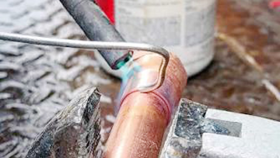
Image by thebuildingexpt
Materials That Control Joint Strength and Code Compliance
The alloy and flux you choose dictate flow temperature, wetting behavior, and long-term corrosion resistance on potable water lines.
Lead-Free Solder Alloys and Their Melting Ranges
Use only lead-free solder meeting ASTM B32 for any drinking-water system. Common options include 95/5 tin-antimony (melting range approximately 450–464 °F), 97/3 tin-copper (440–572 °F), and silver-bearing alloys such as those containing tin, copper, bismuth, and silver (often 420–460 °F).
The lower-melting silver-bearing grades give beginners a wider working window before flux burns off. Higher-antimony or copper formulations produce slightly stronger joints under thermal cycling but require more precise heat control. Never use 50/50 tin-lead on potable lines; residual lead exceeds Safe Drinking Water Act limits.
Flux Selection for Capillary Action
Water-soluble flux meeting ASTM B813 cleans residual oxides, protects the surface during heating, and rinses cleanly after soldering. Tinning flux contains finely ground solder particles that improve wetting on larger fittings or slightly imperfect surfaces.
Apply only a thin, even coat; excess flux produces corrosive residue and can create gas pockets. Petroleum-based fluxes are acceptable on non-potable lines but leave residues that require thorough wiping and flushing.
Torch Fuel and Tip Size Decisions
A standard propane torch with a pencil or medium tip supplies adequate heat for ½-inch and ¾-inch Type L or M copper.
MAP-Pro (propylene) fuel reaches soldering temperature faster on 1-inch and larger fittings or when ambient temperatures are low. Match tip size to pipe diameter: oversized tips overheat small fittings and burn flux before solder can flow.
Preparing Surfaces So Solder Bonds Without Voids
Surface condition determines whether capillary action occurs at all.
Cutting Square and Removing Burrs
A tubing cutter produces a square end with minimal deformation. Rotate the tool while gradually tightening the cutting wheel until the pipe separates cleanly. Immediately ream the interior edge with the cutter’s built-in reamer or a separate deburring tool.
Internal burrs restrict flow, create turbulence, and leave gaps that solder cannot fill completely. File or sand any external ridge left by the cutter so the pipe seats fully against the fitting stop.
Achieving Bright Copper on Both Mating Surfaces
Clean the exterior of the pipe end for the full insertion depth (typically ½ to ¾ inch on ½-inch fittings) using emery cloth, 120-grit abrasive, or a dedicated pipe cleaning brush until the surface shows uniform bright copper.
Clean the interior of the fitting cup with a fitting brush or rolled abrasive until equally bright. Skin oils, oxidation, or residual cutting oil prevent wetting; do not touch the cleaned surfaces after preparation. If more than 30–60 minutes pass before soldering, re-clean because copper oxidizes rapidly in air.
Flux Application and Joint Assembly Timing
Flux must remain active until the moment solder melts.
Correct Quantity and Coverage
Brush a thin continuous film of flux onto the cleaned pipe exterior and the full interior of the fitting cup. Coverage must reach the depth of the socket without excess that will drip into the pipe bore. Excess flux carbonizes under heat and leaves corrosive deposits; insufficient flux allows re-oxidation before solder flows.
Seating and Alignment Before Heat
Insert the pipe fully into the fitting until it contacts the internal stop, then rotate a quarter turn to distribute flux evenly. Wipe any external excess immediately.
Align the assembly so that gravity will not pull molten solder away from the joint during heating. For multi-joint assemblies, dry-fit and mark orientation first; once solder melts, repositioning destroys the joint.
Heating Technique That Triggers Capillary Flow
Heat the fitting, not the solder and not primarily the pipe.
Flame Placement and Even Distribution
Direct the inner blue cone of the flame at the body of the fitting, moving continuously around the circumference. The fitting has greater mass and therefore requires more heat; the pipe receives conducted heat once the fitting reaches temperature.
Aim for roughly 60 % of heat input on the fitting and 40 % on the adjacent pipe. Watch the flux: when it begins to bubble and sizzle, the joint is approaching soldering temperature (approximately 400–500 °F depending on alloy).
Testing Temperature Without Overheating
Touch the solder wire to the joint on the side opposite the flame. If the solder melts on contact and is drawn into the gap, temperature is correct. If it beads or refuses to melt, continue heating briefly.
Blackening or purple discoloration indicates overheating; the flux has burned off and the joint must be cooled, disassembled, re-cleaned, and re-fluxed. Remove the flame as soon as solder begins to flow; residual heat finishes the fill.
Feeding Solder and Reading a Complete Joint
Correct volume and feed location produce a continuous seal.
Quantity and Feed Location
For a ½-inch joint, approximately ¾ inch of ⅛-inch-diameter solder wire is typical; scale roughly with diameter. Feed the solder at the joint interface opposite the flame so capillary action pulls the molten alloy toward the heat source and around the full circumference.
A continuous bright silver ring visible around the outside of the joint indicates complete fill. Excess solder that drips indicates the cup is full; stop feeding.
Vertical and Overhead Adjustments
On vertical joints, start feeding at the bottom and work upward so gravity assists rather than fights capillary action. Overhead joints require slightly faster work and careful heat control to prevent molten solder from dripping away from the cup.
In all positions, maintain a short arc of heat movement so one side does not cool while the opposite side is heated.
Pipe-Size and System Variables That Change Heat Demand
Larger diameters and residual water alter the process window.
Scaling Heat Input with Diameter
½-inch fittings typically reach temperature in 15–30 seconds with propane. ¾-inch fittings require 30–45 seconds. 1-inch and larger benefit from MAP-Pro or a larger tip to distribute heat before flux degrades.
Always heat the fitting body first; thin-wall Type M pipe heats faster than Type L and risks localized overheating if the flame remains stationary.
Residual Moisture and Its Effect on Temperature Rise
Even a small volume of water inside the pipe absorbs heat and prevents the joint from reaching soldering temperature.
Fully drain the line, open a downstream faucet, and verify no water remains before applying flux. If water is present, solder will melt on the exterior but fail to penetrate the cup, producing a cold joint that leaks under pressure.
Evaluating and Correcting Incomplete Joints
Visual and pressure indicators reveal whether rework is required.
Visual Indicators of Proper Fill
A continuous, slightly convex silver ring around the entire circumference with no gaps or dark voids confirms capillary fill. Beading or dull, discontinuous solder on the surface indicates insufficient heat or contamination. Black or sooty residue signals burned flux and requires complete disassembly.
Pressure Testing Sequence
Allow the joint to cool naturally to room temperature before introducing water or air pressure. Air testing at low pressure first allows rework without introducing moisture that complicates subsequent soldering.
Once the system holds air, fill with water and inspect under operating pressure. Any weep requires cutting out the joint or carefully reheating, cleaning, and re-soldering after full disassembly.
Wrapping Up
Successful soldering of copper pipe depends on bright, oxide-free surfaces, active flux, and heat applied primarily to the fitting until capillary action draws the correct volume of lead-free solder into the joint.
When the flux bubbles, the solder melts on contact opposite the flame, and a continuous silver ring forms, the joint will hold.
Advanced practice further refines heat input by matching torch tip and fuel to pipe diameter while monitoring interpass temperature on multi-joint assemblies so previously completed joints remain undisturbed.