Leaking refrigerant joints or clogged TXVs after a new install almost always trace back to one of three failures: oxide scale inside the tubing, incomplete capillary fill, or the wrong filler for the joint type.
Learning how to braze copper refrigerant lines correctly prevents those failures by controlling heat, oxygen exposure, and alloy selection under the high pressures and vibration typical of modern systems.
R-410A and similar refrigerants routinely exceed 400 psi; a joint that looks solid on the outside can still shed black copper oxide flakes that migrate into metering devices and compressor oil.
Proper nitrogen purge, surface cleanliness, and alloy choice determine whether the line set lasts the life of the equipment or becomes a callback within two seasons. The decisions below focus on measurable values and field-proven sequences that produce consistent, code-compliant results.
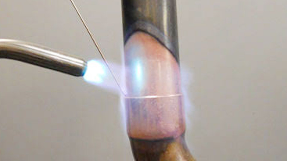
Image by harrisproductsgroup
Choosing the Right Filler Metal for Copper Refrigerant Joints
Filler selection is the first decision that locks in joint strength and ductility under thermal cycling and compressor vibration.
BCuP Alloys for Copper-to-Copper Connections
Phosphorus-copper alloys (AWS BCuP series) are the standard for ACR tubing. The phosphorus content makes them self-fluxing on copper, eliminating external flux and the risk of flux residue inside the system.
BCuP-5 (15 % silver, often sold as Sil-Fos 15 or Stay-Silv 15) is the most common choice for residential and light-commercial line sets.
Its solidus is approximately 1190 °F and liquidus 1475 °F, giving a workable range that fills both tight and slightly open clearances while remaining ductile enough to absorb vibration.
Lower-silver grades such as BCuP-2 (0 % silver) or BCuP-3 (5 % silver) cost less and flow well on close-tolerance joints, but they offer less gap-filling ability and lower ductility. Use them only when fit-up is consistently tight and vibration loads are minimal.
When Silver-Bearing Alloys Become Necessary
Any joint that includes brass, bronze, or steel requires a silver-bearing alloy with external flux. Phosphorus-bearing rods form brittle intermetallics on ferrous metals and wet brass poorly.
Alloys in the 15–45 % silver range (BAg series or high-silver BCuP variants used with flux) provide the necessary wetting and strength.
Apply a thin, even coat of borax-based flux only to the surfaces that will contact the dissimilar metal; excess flux left inside the tubing becomes a contamination source after evacuation.
Clearance and Alloy Flow Characteristics
Ideal joint clearance for capillary action is 0.002–0.005 in. Clearances tighter than 0.001 in restrict flow; clearances larger than 0.006 in require higher-silver, gap-filling alloys and more careful heat control to avoid incomplete fill. BCuP-5 tolerates the upper end of that range better than zero-silver grades.
Why Nitrogen Purge Determines Long-Term System Reliability
Internal oxidation is invisible until the system fails months later. Heating copper above roughly 500 °F in the presence of oxygen produces black cupric oxide scale on the inner wall. POE oils used with R-410A act as solvents and scrub that scale loose, sending particles into TXV screens, capillary tubes, and compressor clearances.
Correct Flow Rates and Setup
Flow dry nitrogen at 2–5 SCFH (approximately 1.5–3 psi at the regulator for most setups). The flow should feel like a faint puff at the open end of the tubing—enough to displace oxygen without cooling the joint or creating back-pressure that pushes molten alloy out of the capillary gap.
Remove Schrader cores and leave an exit path so nitrogen can sweep through the entire circuit. Begin flow before the torch is lit and continue until the joint has cooled below the temperature at which oxide forms.
Consequences of Skipping the Purge
Without nitrogen, scale formation is nearly inevitable on any joint heated to brazing temperature. The particles do not remain attached; they circulate and lodge in the smallest orifices. Manufacturer installation manuals and most system warranties treat nitrogen purge during brazing as a required practice for this reason.
Surface Preparation Decisions That Control Capillary Action
Capillary action fails when oxides, oil, or burrs remain on the faying surfaces. The joint gap is measured in thousandths of an inch; any contaminant thicker than that blocks alloy flow.
Cutting and Deburring Requirements
Cut ACR tubing with a tubing cutter to produce a square end. Ream the interior to remove the ridge left by the cutter; an unreame d burr creates turbulence and local erosion once refrigerant flows. Lightly chamfer the exterior edge only enough to ease insertion into the fitting. Do not leave deep score marks from the cutter wheel.
Cleaning to Bright Metal
Abrade the outside of the tube and the inside of the fitting socket with emery cloth or a dedicated fitting brush until the copper is uniformly bright. Clean at least 1 in beyond the eventual joint line.
Wipe with a clean, lint-free cloth; avoid solvents that leave residue unless they are specifically approved for refrigeration work and fully evaporated. Oil from hands or residual cutting fluid will prevent wetting.
Fit-Up Verification
Dry-fit the tube into the fitting. It should seat fully against the stop with light resistance and no rocking. Excessively loose fits require higher-silver alloy or re-cutting; forced fits risk scoring that later becomes a leak path.
Torch Selection and Flame Control for ACR Tubing
Heat input must raise the joint to brazing temperature quickly enough to limit oxide formation while remaining below the melting point of copper (1984 °F).
Oxy-Acetylene Versus Air-Acetylene
Oxy-acetylene delivers a concentrated flame near 5700 °F and is preferred for larger diameters or cold ambient conditions because heat is applied faster and travels less distance down the tube.
Set a neutral or slightly carburizing flame (sharp inner cone, no outer haze). Typical starting pressures are 5 psi acetylene and 5–10 psi oxygen, adjusted for tip size.
Air-acetylene systems with swirl tips (TurboTorch style) reach approximately 2400–3000 °F and are adequate and more portable for residential line sets up to ⅞ in. Match tip size to tube diameter: smaller tips (#1–#2) for ¼–½ in, larger for ¾ in and above.
Heating Pattern and Temperature Indicators
Keep the flame in continuous motion. Heat the fitting first because it has greater mass, then move to the tube wall adjacent to the socket. The target appearance is a dull red to dark cherry color, corresponding roughly to 1100–1300 °F.
At that point the copper itself supplies the heat that melts the filler. An oxidizing flame blackens the surface and must be corrected immediately by reducing oxygen flow.
Heating Sequence and Filler Application Technique
The sequence determines whether alloy is drawn fully into the capillary gap or merely sits as a surface fillet.
Sequence for Horizontal and Vertical Joints
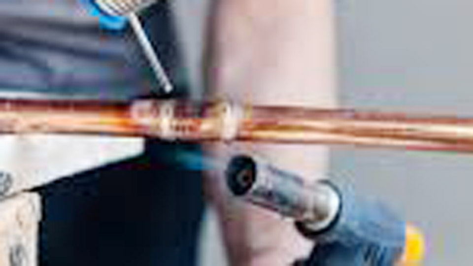
For horizontal joints, begin heating on the underside so the first alloy applied forms a dam that prevents runoff. For vertical joints, start at the bottom and work upward. Once the joint reaches temperature, touch the end of the BCuP rod to the tube-to-fitting interface opposite the flame.
The alloy should melt from the heat of the copper and disappear into the gap by capillary action. Feed continuously until a continuous, smooth fillet appears around the entire circumference. Do not melt the rod in the flame; that burns off phosphorus and silver and produces a weak, porous deposit.
Quantity and Visual Acceptance
A ¾ in joint typically consumes 2–3 in of ⅛ in diameter rod. Excess alloy outside the joint does not increase strength and can mask incomplete internal fill. The finished fillet should be slightly concave to flat, continuous, and free of pinholes or black scale.
Heat Protection for Adjacent Components
When brazing near valves, TXV bulbs, or compressor connections, wrap wet rags or commercial heat-blocking putty around the protected area. Never apply the torch flame directly to a TXV sensing bulb or electronic expansion valve body.
Joint Inspection, Cooling, and Pressure-Testing Criteria
Visual acceptance is only the first filter. Pressure testing under nitrogen confirms integrity before evacuation and charging.
Cooling Under Continuous Purge
Allow the joint to cool naturally while nitrogen continues to flow. Quenching with water or compressed air can induce thermal stress cracks and draws oxygen back into the tubing. Once the joint is cool to the touch, the nitrogen can be stopped and the system prepared for pressure test.
Pressure Test Protocol
Pressurize the completed line set with dry nitrogen to a value appropriate for the system (commonly 150–300 psi for residential, higher for some commercial designs). Hold for 10–15 minutes and monitor a calibrated gauge. Acceptable loss is typically no more than 1–2 psi.
Soap-solution testing of every joint under pressure reveals external leaks that visual inspection misses. Only after a successful hold is the system evacuated to the micron level required by the manufacturer (often 500 microns or lower, held for a specified time).
Repair of Defective Joints
A joint that fails pressure test must be reheated, residual alloy cleaned if necessary, and re-brazed with fresh filler. Grinding or cutting out the joint is preferred when the original alloy has been overheated or contaminated.
Handling Copper-to-Brass and Valve Connections
Service valves, Schrader fittings, and some distributors are brass. These joints require different alloy and flux decisions than pure copper-to-copper work.
Alloy and Flux Requirements
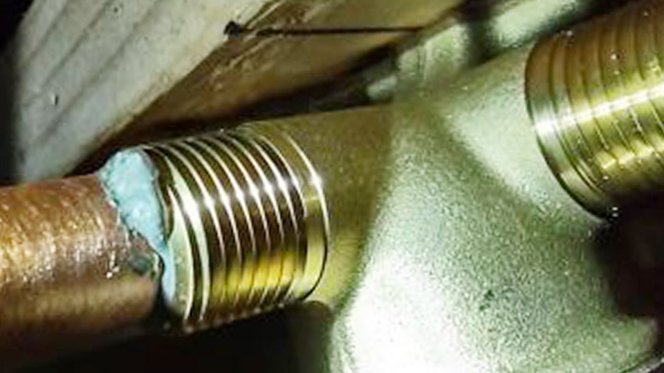
Switch to a silver-bearing alloy (minimum 15 % silver, often 45 % for critical valves) and apply a thin layer of compatible flux to both the copper tube and the brass surface. Phosphorus-copper rods alone are unsuitable.
Heat the brass carefully; its lower thermal conductivity can cause the copper to reach temperature first, leading to overheating of the tube while the brass remains too cool for proper wetting.
Sequence Adjustments Near Valves
Protect the valve body and any plastic or electronic components with heat-blocking materials. Maintain nitrogen flow through the open valve ports. After brazing, thoroughly clean external flux residue to prevent corrosion under insulation.
Wrapping Up
When the filler is selected for the metals present, the nitrogen flow is held at 2–5 SCFH from first heat through cool-down, the surfaces are bright and the clearance is correct, and the alloy is drawn by capillary action rather than forced by the flame, the resulting joint routinely exceeds the strength of the copper tube itself.
The advanced decision that separates reliable installations from callbacks is treating nitrogen purge and alloy selection as non-negotiable process controls rather than optional extras; that single mindset change eliminates the majority of post-install contamination and leak failures seen in the field.
FAQs
Do I need to purge with nitrogen when brazing copper refrigerant lines?
Yes. Flow dry nitrogen at 2–5 SCFH continuously during heating and cooling. Without it, internal copper oxide forms and later circulates into TXVs and the compressor.
What brazing rod should I use for copper-to-copper refrigerant lines?
BCuP-5 (15 % silver) is the standard choice. It is self-fluxing on copper, fills moderate gaps, and provides the ductility needed for vibration and thermal cycling.
Can I use a propane or MAPP torch instead of oxy-acetylene?
Air-fuel torches work for small residential lines (½ in and under) but heat more slowly and transfer heat farther down the tube. Oxy-acetylene or air-acetylene swirl tips give better control on most ACR work.
How do I know the joint is hot enough to add the filler rod?
The copper should show a dull red to dark cherry color (approximately 1100–1300 °F). At that point the heat of the metal, not the flame, melts the rod and capillary action draws the alloy into the joint.